6
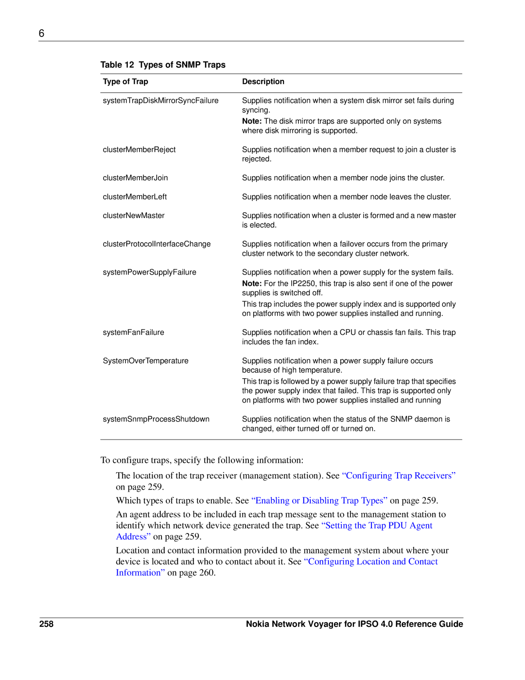
Table 12 Types of SNMP Traps
Type of Trap | Description |
|
|
systemTrapDiskMirrorSyncFailure | Supplies notification when a system disk mirror set fails during |
| syncing. |
| Note: The disk mirror traps are supported only on systems |
| where disk mirroring is supported. |
clusterMemberReject | Supplies notification when a member request to join a cluster is |
| rejected. |
clusterMemberJoin | Supplies notification when a member node joins the cluster. |
clusterMemberLeft | Supplies notification when a member node leaves the cluster. |
clusterNewMaster | Supplies notification when a cluster is formed and a new master |
| is elected. |
clusterProtocolInterfaceChange | Supplies notification when a failover occurs from the primary |
| cluster network to the secondary cluster network. |
systemPowerSupplyFailure | Supplies notification when a power supply for the system fails. |
| Note: For the IP2250, this trap is also sent if one of the power |
| supplies is switched off. |
| This trap includes the power supply index and is supported only |
| on platforms with two power supplies installed and running. |
systemFanFailure | Supplies notification when a CPU or chassis fan fails. This trap |
| includes the fan index. |
SystemOverTemperature | Supplies notification when a power supply failure occurs |
| because of high temperature. |
| This trap is followed by a power supply failure trap that specifies |
| the power supply index that failed. This trap is supported only |
| on platforms with two power supplies installed and running |
systemSnmpProcessShutdown | Supplies notification when the status of the SNMP daemon is |
| changed, either turned off or turned on. |
|
|
To configure traps, specify the following information:
The location of the trap receiver (management station). See “Configuring Trap Receivers” on page 259.
Which types of traps to enable. See “Enabling or Disabling Trap Types” on page 259.
An agent address to be included in each trap message sent to the management station to identify which network device generated the trap. See “Setting the Trap PDU Agent Address” on page 259.
Location and contact information provided to the management system about where your device is located and who to contact about it. See “Configuring Location and Contact Information” on page 260.
258 | Nokia Network Voyager for IPSO 4.0 Reference Guide |