A50010-Y3-C150-2-7619
Umncli
Important Notice on Product Safety
Surpass hiD 6615 S223/S323 R1.5
A50010-Y3-C150-2-7619
Issue History
Reason for Update
Summary System software upgrade added
Details
Contents
4.4
4.3
5.1
5.2
7.2
7.1
7.3
12.1
101
100
102
103
125
124
126
127
147
Surpass hiD 6615 S223/S323 R1.5 3.1
149
150
180
179
181
182
216
Surpass hiD 6615 S223/S323 R1.5 5.9
217
6.1
1.17
1.16
246
247
268
Surpass hiD 6615 S223/S323 R1.5 3.2
269
3.8
297
295
298
299
318
Surpass hiD 6615 S223/S323 R1.5 10.1.1
10.1.1.1
10.1.1.2
353
10.2.12
10.2.13
354
Illustrations
Igmp Snooping and PIM-SM Configuration Network 279
Tab
Tables
171
176
Document Structure
Audience
Tab .1 briefly describes the structure of this document
Tab .1 Overview of Chapters A50010-Y3-C150-2-7619
Document Convention
Tab .2 Command Notation of Guide Book
Document Notation
CE Declaration of Conformity
GPL/LGPL Warranty and Liability Exclusion
System Overview
Quality of Service QoS
System Features
Multicasting
IP Routing
Link Aggregation Trunking
Spanning Tree Protocol STP
System Management based on CLI
Broadcast Storm Control
Radius and TACACS+
Command Mode
Command Line Interface CLI
Shows hiD 6615 S323 software mode structure briefly
Privileged Exec Enable Mode
Privileged Exec View Mode
Global Configuration Mode
Tab .1 Main Commands of Privileged Exec View Mode
Tab .3 Main Commands of Global Configuration Mode
Bridge Configuration Mode
Rule Configuration Mode
Tab .4 Main Commands of Bridge Configuration Mode
Opens Rule Configuration mode
Dhcp Option 82 Configuration Mode
Dhcp Configuration Mode
Tab .6 Main Commands of Dhcp Configuration Mode
Command Mode Description Ip dhcp pool Pool
Interface Configuration Mode
Rmon Configuration Mode
Command Mode Description Interface Interface
Vrrp Configuration Mode
Router Configuration Mode
Tab .10 Main Commands of Router Configuration Mode
Command Mode Description
Route-Map Configuration Mode
Variables following after the commands
Listing Available Commands
Useful Tips
6615 S223/S323
Calling Command History
Command
Surpass hiD 6615 S223/S323 R1.5
Using Command of Privileged Exec Enable Mode
Using Abbreviation
Tab .13 Command Abbreviation
SWITCH# show clock
Exit Current Command Mode
Exits to Privileged Exec enable mode
Able mode, you will be logged out
System Login
System Connection
Step
Password for Privileged Exec Mode
Command Mode Description Passwd enable Password
Passwd enable 8 Password
Changing Login Password
Management for System Account
Creating System Account
To display the created account, use the following command
Configuring Security Level
SWITCH# show list
No privilege configure level
Command Mode Description No privilege
No privilege rmon-alarm level
No privilege bgp level
Shows a configured security level
Command Mode Description Show privilege
SWITCH# write memory
Telnet Access
SWITCH# disconnect ttyp0
Limiting Number of User
Manual System Rebooting
System Rebooting
SWITCHconfig# show exec-timeout
Auto Log-out
Auto System Rebooting
System Authentication
Auto-reset memory 1-120
No auto-reset cpu memory
Authentication Method
Authentication Interface
Primary Authentication Method
Timeout of Authentication Request
Radius Server for System Authentication
Radius Server
Radius Server Priority
Tacacs Server
Tacacs Server for System Authentication
Frequency of Retransmit
5.2 Tacacs Server Priority
TCP Port for the Authentication
Additional TACACS+ Configuration
Authentication Type
Command Mode Description Login tacacs timeout
Displaying System Authentication
Accounting Mode
Login accounting-mode none
Start stop both
Tacacs
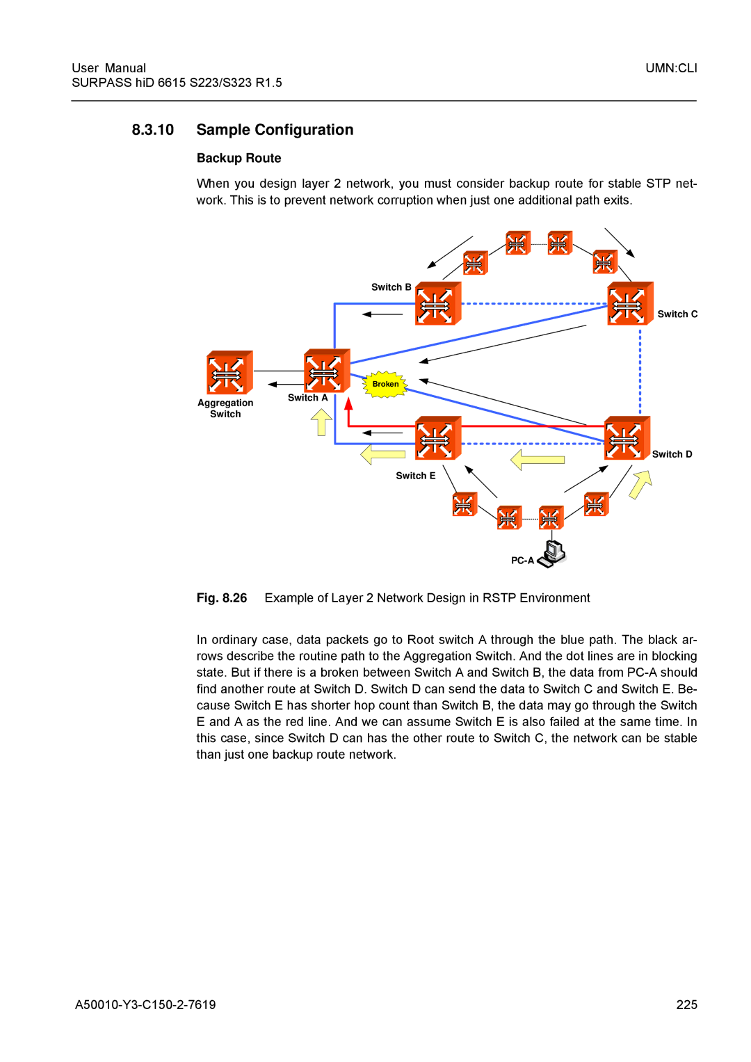
Sample Configuration
Assigning IP Address
To enable the interface, use the following command
Interface Configuration Mode
Enabling Interface
Disabling Interface
Assigning IP Address to Network Interface
Static Route and Default Gateway
Ip address IP-ADDRESS/M
No ip route IP-ADDRESS/M
Forwarding Information BaseFIB Retain
Displaying Forwarding Information BaseFIB Table
Displaying Interface
② On Interface Configuration Mode
Show interface Interface
Show ip interface Interface
SSH Server
SSH Secure Shell
Login to SSH Server
Assigning Specific Authentication Key
2.3 Configuring Authentication Key
SSH Client
Configure the authentication key in the switch
Connect to SSH server with the authentication key
Ssh keygen rsa1 rsa dsa
802.1x Authentication
Server Suppliant Authenticator Authentication Server
EAP over LAN EAP over Radius
Configuring Radius Server
1 802.1x Authentication
Authentication Server
Designate as default Response
Configuring Authentication Mode
Command Mode Description Dot1x radius-server move IP
Dot1x radius-server host
Force Authorization
Authentication Port
Mode Description Dot1x port-control auto force
Command Mode Description Dot1x timeout tx-period
1.7 Configuring Number of Request to Radius Server
2 802.1x Re-Authentication
1.8 Configuring Interval of Request to Radius Server
Enabling 802.1x Re-Authentication
Configuring the Interval of Re-Authentication
Configuring the Interval of Requesting Re-authentication
2.4 802.1x Re-authentication
Applying Default Value
Initializing Authentication Status
Displaying 802.1x Configuration
6 802.1x User Authentication Statistic
SWTICHconfig# dot1x auth-mode mac-base
SWTICHconfig# dot1x system-auth-control
PortAuthed
Port Basic
Selecting Port Type
Show port Ports
To enable/disable a port, use the following command
Ethernet Port Configuration
Command Mode Description Port medium Port sfp rj45
Enabling Ethernet Port
Auto-negotiation
Command Mode Description Port nego Ports on off
Transmit Rate
Port speed Ports 10 100
Command Mode Description Port duplex Ports full half
Duplex Mode
Flow Control
Half
To view description of port, use the following command
Following is an example of configuring flow control to port
SWITCHbridge# port flow-control 25 on
SWITCHbridge# show port description
SWITCHbridge# show port statistics rmon
SWITCHbridge# show port statistics avg-pkt
Traffic Statistics
Packets Statistics
To enable/disable protocol statistics
CPU statistics
Protocol statistics
SWITCH# show port
To display a port status, use the following command
Port Mirroring
Port Status
Designate the monitor port, use the following command
Activate the port mirroring, using the following command
Designate the mirrored ports, use the following command
Command Mode Description Mirror add Ports ingress
Connect a motoring PC to the monitor port of the switch
To disable monitoring function, use the following command
Enable mirroring function
Configure the monitor port 1 and mirroring port 2, 3, 4
Environment Configuration
Host Name
Time and Date
Network Time Protocol
Time Zone
Tab .1 shows the world time zone
Tab .1 World Time Zone
NTP Network Time Protocol
Simple Network Time Protocol Sntp
Following is an example of releasing NTP and showing it
Terminal Configuration
To display Sntp configuration, use the following command
No sntp
To restore a default banner, use the following command
Login Banner
To set a DNS server, use the following command
DNS Server
Disabling Daemon Operation
Fan Operation
System Threshold
CPU Load
Port Traffic
Mode Description Threshold Port
Fan Operation
No threshold Port Ports rx
Enabling FTP Server
System Temperature
System Memory
Threshold temp Value Value
Displaying System Configuration
Configuration Management
Assigning IP Address of FTP Client
All Option History router bgp pim rip
System Configuration File
Saving System Configuration
SWITCH# show running-config syslog
Auto-Saving
Restoring Default Configuration
To delete backup file, use the following command
SWITCHconfig# copy running-config SURPASShiD6615
SWITCHconfig# restore factory-defaults
System Management
Network Connection
Figured time interval. Default is 2 seconds
Items Description Source address or interface
Type of service
Set DF bit in IP header? no
Data pattern 0xABCD
IP Source Routing A50010-Y3-C150-2-7619
IP Icmp Source-Routing
Following is the basic information to trace packet routes
Tracing Packet Route
Displaying User Connecting to System
SWITCH# traceroute
MAC Table
SWITCH# show uptime
Configuring Ageing time
Running Time of System
System Information
CPU packet limit
System Memory Information
Average of CPU Load
Running Process
Displaying Installed OS
Default OS
Displaying System Image
Tech Support
Switch Status
Ber of display lines of terminal screen
A50010-Y3-C150-2-7619 103
Simple Network Management Protocol Snmp
Command Mode Description Snmp community ro rw Community
Snmp Community
No snmp community ro rw Community
Information of Snmp Agent
Following is an example of creating 2 Snmp communities
A50010-Y3-C150-2-7619 105
SWITCHconfig# show snmp com2sec
Following is an example of configuring Snmp com2sec
Snmp Com2sec
Snmp Group
SWITCHconfig# snmp view Test included
Permission to Access Snmp View Record
Snmp View Record
Following is an example of creating an Snmp view record
To display Snmp version 3 user, use the following command
Lowing command
Snmp access
Snmp Version 3 User
To set an Snmp trap host, use the following command
Snmp Trap Mode
To select an Snmp trap-mode, use the following command
Snmp Trap Host
110 A50010-Y3-C150-2-7619
Enabling Snmp Trap
To disable Snmp trap, use the following command
Disabling Snmp Trap
Node
Enabling Alarm Notification
Snmp Alarm
SWITCHconfig# snmp inform-trap-host
Displaying Snmp Trap
Default Alarm Severity
Alarm Severity Criterion
To configure a priority of alarm, use the following command
114 A50010-Y3-C150-2-7619
Generic Alarm Severity
Snmp Alarm-severity adva-if-sfp-mismatch
Adva Alarm Severity
A50010-Y3-C150-2-7619 115
Critical major minor warning intermedi
116 A50010-Y3-C150-2-7619
ERP Alarm Severity
Displaying Snmp Configuration
STP Guard Alarm Severity
A50010-Y3-C150-2-7619 117
To disable Snmp feature, use the following command
SWITCHconfig# show snmp alarm-history
Disabling Snmp
Disables local OAM
Operation, Administration and Maintenance OAM
OAM Loopback
A50010-Y3-C150-2-7619 119
Local OAM Mode
OAM Unidirection
Remote OAM
Displaying OAM Configuration
To display OAM configuration, use the following command
A50010-Y3-C150-2-7619 121
122 A50010-Y3-C150-2-7619
Lldp Operation
Link Layer Discovery Protocol Lldp
Lldp Operation Type
Basic TLV
Interval and Delay Time
Lldp Message
124 A50010-Y3-C150-2-7619
Displaying Lldp Configuration
To display Lldp configuration, use the following command
A50010-Y3-C150-2-7619 125
SWITCHconfig# show rmon-history config
To open RMON-historymode, use the following command
Command Mode Description Rmon-history
Remote Monitoring Rmon
Subject of Rmon History
Source Port of Statistical Data
Number of Sample Data
Interval of Sample Inquiry
Deleting Configuration of Rmon History
Activating Rmon History
Displaying Rmon History
Subject of Rmon Alarm
Rmon Alarm
Command Mode Description Rmon-alarm
A50010-Y3-C150-2-7619 129
Absolute Comparison and Delta Comparison
Object of Sample Inquiry
Upper Bound of Threshold
130 A50010-Y3-C150-2-7619
Lower Bound of Threshold
Configuring Standard of the First Alarm
Deleting Configuration of Rmon Alarm
Activating Rmon Alarm
Displaying Rmon Alarm
Rmon Event
Subject of Rmon Event
Event Description
Event Type
Activating Rmon Event
Displaying Rmon Event
Deleting Configuration of Rmon Event
134 A50010-Y3-C150-2-7619
Activates Rmon event
Syslog
To set a syslog output level, use the following command
Syslog Output Level
Syslog Output Level without a Priority
136 A50010-Y3-C150-2-7619
Syslog Output Level with a Priority
Local5 local6 local7 lpr mail news sys
Log user uucp emerg alert crit err
Facility Code
Syslog Bind Address
A50010-Y3-C150-2-7619 137
Debug Message for Remote Terminal
Displaying Syslog Configuration
Disabling Syslog
Displaying Syslog Message
Rule and QoS
How to Operate Rule and QoS
Rule Creation
Rule Configuration
Rule Priority
140 A50010-Y3-C150-2-7619
A50010-Y3-C150-2-7619 141
Packet Classification
Tcp
142 A50010-Y3-C150-2-7619
A50010-Y3-C150-2-7619 143
Rule Action
Overwrites 802.1p CoS field in the packet same as IP
144 A50010-Y3-C150-2-7619
Applying Rule
Modifying and Deleting Rule
Remedy Select another name for the rule e.g. add a prefix
Displaying Rule
3 QoS
Weighted Round Robin WRR
Weighted Fair Queuing WFQ
Scheduling Algorithm
Strict Priority Queuing SP
Weighted Fair Queuing
3.3 802.1p Priory-to-queue Mapping
Qos Weight
To configure a queue parameter, use the following command
Admin Access Rule
To display a configuration of QoS, enter following command
Queue Parameter
Command Mode Description Priority low medium high
Command Mode Description Rule Name create admin
A50010-Y3-C150-2-7619 151
Highest Defaul low
152 A50010-Y3-C150-2-7619
Command Mode Description Apply
Command Mode Description No-match deny
Applies an admin access rule to the system
Match permit Permits a packet
154 A50010-Y3-C150-2-7619
Shows a current configuration of a rule
NetBIOS Filtering
Internet
A50010-Y3-C150-2-7619 155
SWITCHbridge# show netbios-filter
Martian Filtering
Max Host
To display configured max host, use the following command
Following is an example of displaying configured max hosts
Max New Hosts
Enable port security on the port
To configure max new hosts, use the following command
Port Security
Port Security on Port
Set the maximum number of secure MAC address for the port
Set the violation mode and the action to be taken
Enter a secure MAC address for the port
A50010-Y3-C150-2-7619 159
Port Security Aging
This is an example of configuring port security on port
Port
Maximum
A50010-Y3-C150-2-7619 161
MAC Table
Command Mode Description No mac
Command Mode Description Clear mac
Clear mac Name
Clear mac Name Port
Sample Configuration
Default Policy of MAC Filtering
MAC Filtering
Adding Policy of MAC Filter
Deleting MAC Filter Policy
Listing of MAC Filter Policy
Displaying MAC Filter Policy
Address Resolution Protocol ARP
Following is an example of displaying one configuration
ARP Table
Registering ARP Table
Displaying ARP Table
166 A50010-Y3-C150-2-7619
ARP Alias
To display ARP alias, use the following command
ARP Inspection
A50010-Y3-C150-2-7619 167
168 A50010-Y3-C150-2-7619
Icmp Message Control
Gratuitous ARP
Proxy-ARP
Interval for Transmit Icmp Message
Blocking Echo Reply Message
Tab
Type Value
Type Status
Enable Shows Icmp interval configuration Global
Command Mode Description Ip icmp interval rate-limit
Transmitting Icmp Redirect Message
172 A50010-Y3-C150-2-7619
RST Configuration
IP TCP Flag Control
Policy of unreached messages
SYN Configuration
Packet Dump
Verifying Packet Dump
Packet Dump by Protocol
Packet Dump with Option
A50010-Y3-C150-2-7619 175
Tab .4 shows the options for packet dump
Tab .4 Options for Packet Dump 176 A50010-Y3-C150-2-7619
Option Description
Displaying the usage of the packet routing table
Debug Packet Dump
A50010-Y3-C150-2-7619 177
Enlarged Network Bandwidth
Vlan
Cost-Effective Way
Strengthened Security
Port-Based Vlan
Specifying Pvid
Creating Vlan
Assigning Port to Vlan
Deleting Vlan
Protocol-Based Vlan
MAC address-based Vlan
Displaying Vlan
Tagged Vlan
Subnet-based Vlan
Vlan Tag
Macbase MAC-ADDRESS
Vlan Description
Displaying Vlan Information
Mapping Frames to Vlan
Tunnel Port
QinQ
Trunk Port
Tagged
To disable double tagging, use the following command
Double Tagging Configuration
Double Tagging Operation
Designate the QinQ port
Layer 2 Isolation
Tpid Configuration
Private Vlan Edge
Private Vlan
Port Isolation
Command Mode Description Port protected Ports
Shared Vlan
No port protected Ports
Vlan fid Vlans FID
188 A50010-Y3-C150-2-7619
Open Bridge Configuration mode using the bridge command
Open Rule Configuration mode using rule Name create command
Sample Configuration 1 Configuring Port-based Vlan
Vlan Translation
Following is deleting vlan id 3 among configured Vlan
Sample Configuration 2 Deleting Port-based Vlan
Sample Configuration 3 Configuring Protocol-based Vlan
Default br2 br3 br4
Switch
Sample Configuration 4 Configuring QinQ
Sample Configuration 5 Configuring Shared Vlan with FID
SWITCHbridge# vlan dot1q-tunnel enable
Link Aggregation
SWITCHbridge# vlan add br5 1-42untagged
Port Trunk
Configuring Port Trunk
Trunk distmode
Dstip dstmac Srcdstip
Displaying Port Trunk Configuration
Link Aggregation Control Protocol Lacp
Disabling Port Trunk
Configuring Lacp
Activate Lacp function, using the following command
Packet Route
Operating Mode of Member Port
To disable configuring packets, use the following command
196 A50010-Y3-C150-2-7619
Bpdu Transmission Rate
Identifying Member Ports within Lacp
Key value of Member Port
A50010-Y3-C150-2-7619 197
Command Mode Description Lacp port priority Ports
Priority of Switch
Priority of Member Port
198 A50010-Y3-C150-2-7619
Displaying Lacp Configuration
To display a configured LACP, use the following command
A50010-Y3-C150-2-7619 199
Spanning-Tree Protocol STP
Root Switch
STP Operation
A50010-Y3-C150-2-7619 201
Switch
Designated Switch
Port Priority
Designated Port and Root Port
Port States
Disabled
Listening
Learning
Backup
Switch B Switch C
Port Path Switch D
Rstp Operation
Rapid Network Convergence
Bpdu Policy
17 Network Convergence of 802.1w A50010-Y3-C150-2-7619 207
19 Network Convergece of 802.1w 208 A50010-Y3-C150-2-7619
Compatibility with 802.1d
Mstp Operation
Switch D Switch E
Operation
Region B IST
Configuring STP/RSTP/MSTP/PVSTP/PVRSTP Mode Required
Region a IST
A50010-Y3-C150-2-7619 211
Root Switch
Configuring STP/RSTP/MSTP
Activating STP/RSTP/MSTP
Path-cost
Port-priority
Tab STP Path-cost
A50010-Y3-C150-2-7619 213
MST Region
Point-to-point MAC Parameters
Mstp Protocol
Edge Ports
A50010-Y3-C150-2-7619 215
To delete the edge port mode, use the following command
Displaying Configuration
Command Mode Description Stp pvst enable VLAN-RANGE
Configuring PVSTP/PVRSTP
Activating PVSTP/PVRSTP
A50010-Y3-C150-2-7619 217
6.3 Path-cost
Ally. To configure port priority, use the following command
6.4 Port-priority
218 A50010-Y3-C150-2-7619
Root Guard Configuration
Root Guard
Restarting Protocol Migration
Forward Delay
Bridge Protocol Data Unit Configuration
Hello Time
Hello Time
Max Age
Forward Delay
Following command
To delete a configured max age, use the following command
9.4 Bpdu Hop
9.5 Bpdu Filter
Configure the specific port as edge-port
Configure Bpdu Guard
Self Loop Detection
224 A50010-Y3-C150-2-7619
Displaying Bpdu Configuration
Backup Route
Mstp Configuration
SWITCHbridge# stp force-version mstp
226 A50010-Y3-C150-2-7619
Internet
Virtual Router Redundancy Protocol Vrrp
To delete the Vrrp configuration, use the following command
Configuring Vrrp
Associated IP Address
228 A50010-Y3-C150-2-7619
Access to Associated IP Address
Master Router and Backup Router
A50010-Y3-C150-2-7619 229
SWTICH1config# router vrrp default
Layer 3 Switch 2 IP Address 10.0.0.2/24
Vrrp Track Function
To configure Vrrp Track, use the following command
Authentication Password
Preempt
SWITCHconfig-vrrp#authentication cleartext network
Following is an example of disabling Preempt
A50010-Y3-C150-2-7619 233
Configuration mode
Rate Limit
Vrrp Statistics
Configuring Rate Limit
To set a port bandwidth, use the following command
A50010-Y3-C150-2-7619 235
Configuring Flood-Guard
Flood Guard
236 A50010-Y3-C150-2-7619
SWITCHbridge# show mac-flood-guard
Following is an example of configuration to bandwidth as
Bandwidth
A50010-Y3-C150-2-7619 237
Saving Cost
Dynamic Host Configuration Protocol Dhcp
Efficient IP Management
IP Packet Broadcast Dhcp Server or Relay Agent
Dhcp Server
Dhcp Pool Creation
Dhcp Subnet
Range of IP Address
Following is an example of specifying the default gateway
Default Gateway
IP Lease Time
A50010-Y3-C150-2-7619 241
Manual Binding
DNS Server
Following is an example of specifying a DNS server
242 A50010-Y3-C150-2-7619
Dhcp Server Option
Domain Name
Static Mapping
Recognition of Dhcp Client
Command Mode Description Ip dhcp arp ping timeout
Command Mode Description Ip dhcp arp ping packet
IP Address Validation
Authorized ARP
Prohibition of 1N IP Address Assignment
Ignoring Bootp Request
Dhcp Packet Statistics
A50010-Y3-C150-2-7619 245
SWITCHconfig# show ip dhcp server statistics
Displaying Dhcp Pool Configuration
Command Mode Description Show ip dhcp pool Pool
246 A50010-Y3-C150-2-7619
Dhcp Class Capability
Dhcp Address Allocation with Option
Dhcp Class Creation
Relay Agent Information Pattern
Range of IP Address for Dhcp Class
Associating Dhcp Class
Text String
No address range A.B.C.D
Dhcp Database Agent
Dhcp Lease Database
Displaying Dhcp Lease Status
A50010-Y3-C150-2-7619 249
Deleting Dhcp Lease Database
Dhcp Relay Agent
Dhcp Server Relay Agent Subnet
PC= Dhcp Client
Packet Forwarding Address
Smart Relay Agent Forwarding
C.D all
Dhcp Option
Option 82 Sub-Option
Enabling Dhcp Option
Default Trust Policy
Option 82 Reforwarding Policy
Option 82 Trust Policy
Simplified Dhcp Option
To specify a trusted remote ID, use the following command
Trusted Remote ID
Trusted Physical Port
Enabling Dhcp Client
Dhcp Client
6.2 Dhcp Client ID
6.3 Dhcp Class ID
Requesting Option
Displaying Dhcp Client Configuration
Forcing Release or Renewal of Dhcp Lease
A50010-Y3-C150-2-7619 257
Enabling Dhcp Snooping
Dhcp Snooping
Dhcp Trust State
258 A50010-Y3-C150-2-7619
Dhcp Rate Limit
Mode Description Ip dhcp snooping Limit-lease
Dhcp Lease Limit
Source MAC Address Verification
Specifying Dhcp Snooping Database Agent
Dhcp Snooping Database Agent
Specifying Dhcp Snooping Binding Entry
260 A50010-Y3-C150-2-7619
IP Source Guard
Displaying Dhcp Snooping Configuration
Enabling IP Source Guard
Source IP Address Filter
Source port-security commands together
Displaying IP Source Guard Configuration
Command Mode Description Ip dhcp verify source Ports
Static IP Source Binding
Dhcp Filtering
Command Mode Description Ip dhcp filter-address
Dhcp Packet Filtering
Dhcp Server Packet Filtering
Packet service all
Command Mode Description Debug dhcp filter
Debugging Dhcp
264 A50010-Y3-C150-2-7619
ERP Operation
Ethernet Ring Protection ERP
Send Link Down Message
Normal Node
RM Node
Normal Node RM Node
Configuring ERP
Loss of Test Packet Lotp
ERP Domain
Port of ERP domain
RM Node
Protected Vlan
Protected Activation
Wait-to-Restore Time
Manual Switch to Secondary
Learning Disable Time
Test Packet Interval
Displaying ERP Configuration
Stacking
Show erp all DOMAIN-ID
Designating Master and Slave Switch
Switch Group
Designate Mater switch using the following command
A50010-Y3-C150-2-7619 271
To disable stacking, use the following command
Accessing to Slave Switch from Master Switch
Sample Configuration 1 Configuring Stacking
Disabling Stacking
SWITCHAconfig# stack device default
SWITCHA# configure terminal
SWITCHBconfig# stack device default
A50010-Y3-C150-2-7619 273
To disconnect, input as below
Broadcast Storm Control
Storm-control broadcast mul
Ticast dlf Rate Ports
Command Mode Description Jumbo-frame Ports
Jumbo-frame Capacity
A50010-Y3-C150-2-7619 275
Blocking Direct Broadcast
Maximum Transmission Unit MTU
276 A50010-Y3-C150-2-7619
A50010-Y3-C150-2-7619 277
SWITCHconfig-if#show running-config interface
Layer 3 Network
Layer 2 Network
Multicast Routing Information Base
Command Mode Description Ip multicast route-limit
Enabling Multicast Routing Required
Limitation of Mrib Routing Entry
Clearing Total or Partial Group Entry of Mrib
Clearing Mrib Information
Clearing Statistics of Multicast Routing Table
280 A50010-Y3-C150-2-7619
Displaying Mrib Information
Multicast Time-To-Live Threshold
Mrib Debug
282 A50010-Y3-C150-2-7619
Multicast Aging
Internet Group Management Protocol Igmp
Igmp Basic Configuration
Igmp Version per Interface
Igmp Version
Igmp Version
Igmp Static Join Setting
Removing Igmp Entry
Igmp Debug
Command Mode Description Ip igmp static-group
Igmp Query Configuration
Maximum Number of Groups
Vlan Vlan port Port reporter
286 A50010-Y3-C150-2-7619
Igmp Maximum Response Time
Displaying the Igmp Configuration
Igmp v2 Fast Leave
A50010-Y3-C150-2-7619 287
Step Execute the ip multicast-routing command
Igmp Snooping Basic Configuration
3 L2 Mfib
Enabling Igmp Snooping per Vlan
Command Mode Description Ip igmp snooping vlan Vlans
Enable Igmp snooping on a Vlan interface
Command Mode Description Show ip igmp snooping Vlan
Igmp v2 Snooping
Igmp v2 Snooping Fast Leave
Multicast Packet
290 A50010-Y3-C150-2-7619
Igmp v2 Snooping Querier
To disable Igmp querier, use the following command
Enabling Igmp Snooping Querier
A50010-Y3-C150-2-7619 291
To disable the max-response-time, use the following command
Timeout Value of Igmp v2 Snooping Querier’s General Query
Query Interval of Igmp v2 Snooping Querier
292 A50010-Y3-C150-2-7619
A50010-Y3-C150-2-7619 293
Igmp v2 Snooping Last-Member-Interval
Vlans querier detail
Last-member-query-interval
Igmp v2 Snooping Report Method
Configuring Mrouter Port per Vlan
Mrouter Port
294 A50010-Y3-C150-2-7619
Displaying Mrouter Configuration
Multicast TCN Flooding
Mrouter Port Learning Method
296 A50010-Y3-C150-2-7619
Command Mode Description Ip igmp snooping tcn query
Vlans flood
Nected to on a Vlan interface
Igmp Snooping Version
Igmp v3 Snooping
Join Host Management
A50010-Y3-C150-2-7619 297
To display a configuration, use the following command
Multicast Vlan Registration MVR
Immediate Block
MVR Group Address
Enabling MVR
MVR IP Address
A50010-Y3-C150-2-7619 299
7.5 Displaying MVR Configuration
Igmp Filtering and Throttling
Send and Receive Port
Policy of Igmp Profile
Creating Igmp Profile
Group Range of Igmp Profile
A50010-Y3-C150-2-7619 301
Applying Igmp Profile to the Filter Port
To return to the default setting, use the following command
Max Number of Igmp Join Group
302 A50010-Y3-C150-2-7619
PIM-SM Protocol Independent Multicast-Sparse Mode
Displaying Igmp Snooping Table
RPT and SPT
Packet for the request
PIM Common Configuration
DR Priority
PIM-SM and Passive Mode
Filters of Neighbor in PIM
To configure a query hold time, use the following command
PIM Hello Query
306 A50010-Y3-C150-2-7619
To activate PIM-SM debugging, use the following command
Bootstrap Router BSR
BSR and RP
PIM Debug
Static RP for Certain Group
RP Information
Ip pim bsr-candidate
Global Clears all RP sets Set
A50010-Y3-C150-2-7619 309
Enabling Transmission of Candidate RP Message
4.3
PIM-SM Registration
4.4 Ignoring RP Priority
Rate Limit of Register Message
Command Mode Description Ip pim register-suppression
Configure filtering out multicast sources
Filters for Register Message from RP
Source Address of Register Message
This command is disabled by default
SPT Switchover
Reachability for PIM Register Process
312 A50010-Y3-C150-2-7619
PIM Join/Prune Interoperability
Cisco Router Interoperability
Checksum of Full PIM Register Message
8.2 Candidate RP Message with Cisco BSR
With older Cisco IOS versions, use the following command
8.3 Excluding GenID Option
With older Cisco IOS versions
PIM Snooping
PIM-SSM Group
316 A50010-Y3-C150-2-7619
Displaying PIM-SM Configuration
Border Gateway Protocol BGP
IP Routing Protocol
Basic Configuration
Configuration Type of BGP
Enabling BGP Routing
Advanced Configuration
Go back to Global Configuration mode using the exit command
Disabling BGP Routing
Summary of Path
Command Mode Description Aggregate-address A.B.C.D/M
Automatic Summarization of Path
As-set summary-only
Choosing Best Path
Multi-Exit Discriminator MED
Bgp deterministic-med
No bgp deterministic-med
Command Mode Description Bgp bestpath compare-confed
Command Mode Description Bgp bestpath as-path ignore
Selects the best path using the router ID for identical
Aspath
Graceful Restart
Configures the router to consider the MED in choosing
Restart Time
IP Address Family
Stalepath Time
324 A50010-Y3-C150-2-7619
Default Route
BGP Neighbor
Peer Group
To create a BGP Peer Group, use the following command
Route Map
Force Shutdown
BGP Session Reset
Session Reset of All Peers
Word shutdown
328 A50010-Y3-C150-2-7619
Session Reset of Peers within Particular AS
Session Reset of Specific Route
Session Reset of External Peer
A50010-Y3-C150-2-7619 329
330 A50010-Y3-C150-2-7619
Session Reset of Peer Group
A50010-Y3-C150-2-7619 331
Displaying and Managing BGP
NEIGHBOR-IP routes
332 A50010-Y3-C150-2-7619
Enabling Ospf
Open Shortest Path First Ospf
Command Mode Description Router ospf
334 A50010-Y3-C150-2-7619
No router ospf
Command Mode Description Network A.B.C.D/M area
ABR Type Configuration
Compatibility Support
Ospf Interface
Authentication Type
Authentication Key
336 A50010-Y3-C150-2-7619
A50010-Y3-C150-2-7619 337
Interface Cost
Routing Protocol Interval
Blocking Transmission of Route Information Database
To configure a dead interval, use the following command
To configure a transmit delay, use the following command
A50010-Y3-C150-2-7619 339
Ospf Maximum Transmission Unit MTU
Ospf Priority
340 A50010-Y3-C150-2-7619
Non-Broadcast Network
Ospf Network Type
A50010-Y3-C150-2-7619 341
Area Authentication
Ospf Area
342 A50010-Y3-C150-2-7619
Area 0-4294967295filter-list access LIST-NAMEin out
Default Cost of Area
No area 0-4294967295filter- list access LIST-NAMEin out
Area 0-4294967295filter-list prefix LIST-NAMEin out
Not So Stubby Area Nssa
Default-information-originate
No-redistribution
No-summary
Originate metric Router Configures Nssa with one option
To delete configured NSSA, use the following command
A50010-Y3-C150-2-7619 345
Originate
Shortcut Area
Area Range
346 A50010-Y3-C150-2-7619
C.D/M advertise not Advertise
Virtual Link
Stub Area
Transmit-delay
Dead-interval
348 A50010-Y3-C150-2-7619
To delete the configuration, use the following command
Default Metric
Graceful Restart Support
Hello-interval
Grace-period
Helper
350 A50010-Y3-C150-2-7619
Opaque-LSA Support
Default Route
Metric
Metric-type
Finding Period
Metric-type Router Deletes the configuration
Route-map
Metric-type Always Route-map MAP-NAME
External Routes to Ospf Network
Metric-type Route-map MAP-NAME
A50010-Y3-C150-2-7619 353
Router Deletes the default metric
To delete the default metric, use the following command
Ospf Distance
External Inter-area Intra-area
Host Route
To make it as a default, use the following command
Passive Interface
A50010-Y3-C150-2-7619 355
Blocking Routing Information
Summary Routing Information
Ospf Monitoring and Management
Displaying Ospf Protocol Information
To display the Ospf database, use the following command
A50010-Y3-C150-2-7619 357
As A.B.C.D
358 A50010-Y3-C150-2-7619
Command Mode Description Show ip ospf interface Interface
Displaying Debugging Information
Limiting Number of Database
A50010-Y3-C150-2-7619 359
Maximum Process of LSA
Command Mode Description Overflow database
360 A50010-Y3-C150-2-7619
Overflow database external
Routing Information Protocol RIP
To use RIP protocol, you should enable RIP
Enabling RIP
A50010-Y3-C150-2-7619 361
RIP Neighbor Router
Configure the network to operate as RIP
RIP Version
Redistributing Routing Information
Creating available Static Route only for RIP
Command Mode Description Route-map TAG deny permit
Metrics for Redistributed Routes
Administrative Distance
Originating Default Information
Routing Information Filtering
Filtering Access List and Prefix List
Disabling the transmission to Interface
Offset List
Update
RIP Network Timer
Timeout
Maximum Number of RIP Routes
To adjust the timers, use the following command
Authentication Key
No timers basic Update Time
Split Horizon
To disable RIP authentication, use the following command
Restarting RIP
UDP Buffer Size of RIP
372 A50010-Y3-C150-2-7619
Monitoring and Managing RIP
General Upgrade
Command Mode Description Copy ftp tftp os Download
A50010-Y3-C150-2-7619 373
374 A50010-Y3-C150-2-7619
Boot Mode Upgrade
To configure a default gateway, use the following command
To configure a subnet mask, use the following command
To the boot mode only
A50010-Y3-C150-2-7619 375
376 A50010-Y3-C150-2-7619
Boot load os1 10.27.41.82 V5212G.3.18.x
FTP Upgrade
Uploads the new system software using the following command
A50010-Y3-C150-2-7619 377
Command! For more information, see Section
Exit the FTP client using the following command
Command Mode Description Exit
378 A50010-Y3-C150-2-7619
Address Resolution Protocol
Access Control List
Command Line Interface
CoS Class of Service
Loss of Signal
Internet Service Provider
Loss of Power
Medium Access Control
Spanning Tree Protocol
Type of Service
Software
Transmission Control Protocol