Technical Information
Copyrighted Materials
License Agreements
High Risk Materials
Trademarks
Page
Table of Contents
Table of Contents
AT Commands Reference
G24-L AT Commands Reference Manual April 15
April 15 G24-L AT Commands Reference Manual Iii
Table of Contents
April 15 G24-L AT Commands Reference Manual
Gprs
April 15 G24-L AT Commands Reference Manual Vii
Using the Commands
Tools
Viii G24-L AT Commands Reference Manual April 15
List of Figures
List of Figures
List of Tables
List of Tables
Xii G24-L AT Commands Reference Manual April 15
April 15 G24-L AT Commands Reference Manual Xiii
Xiv G24-L AT Commands Reference Manual April 15
April 15 G24-L AT Commands Reference Manual
Page
Manual Organization
April 15 G24-L AT Commands Reference Manual Xvii
Manual Scope
Target Audience
Text Conventions
Xviii G24-L AT Commands Reference Manual April 15
Applicable Documents
Contact Us
General Safety
Field Service
Manual Banner Definitions
Do not substitute parts or modify equipment
General Safety
Symbol Definition Important safety information will follow
Keep away from live circuits
Disposal of Motorola equipment in non-EU countries
April 15 G24-L AT Commands Reference Manual Xxi
Caring for the Environment
Disposal of Motorola equipment in EU countries
Limitation of Liability
Xxii G24-L AT Commands Reference Manual April 15
Limitation of Liability
CMM Compliance
How to Get Warranty Service?
Warranty Notification
April 15 G24-L AT Commands Reference Manual Xxiii
Claiming
Xxiv G24-L AT Commands Reference Manual April 15
Claiming
Conditions
April 15 G24-L AT Commands Reference Manual Xxv
What is Not Covered by the Warranty
Installed Data
Out of Warranty Repairs
Version Information
Revision History
Manual Number
Manual Title
Overview
Features and Benefits
Connectivity Interface
Gprs Operation
Technical Description
CSD Operation
CSD Operation
SIM Application Toolkit STK
Improved OEM Features
Call Control by SIM
Set up Idle Mode Text
Improved OEM Features
Menu Selection
System Overview
TCP/UDP IP Connection
UDP/IP
Features and Benefits
Sidetone
Audio
Echo Suppression
Improved OEM Features
Features
Short Message Service SMS
Messages
Short Message Service SMS
SMS Type SMS Index Max Number of SMS Incoming messages
Outgoing and CB
UCS2 Character Set Management
Character Sets
Ascii Character Set Management
GSM Character Set Management
Character Sets
Character Set Management
AT Commands
AT Commands Summary
+CLIP
+CRC
Ring
+CRING
+CACM
+CLCC
+MCST
+CAOC
+CPMS
+CCLK
SMS
+CSMS
+CSQ
+CGSMS
+CMGS
+MCSAT
+ICF
+MCWAKE
+MGGIND
+CFUN
This command unlocks or resets the first Plmn Inserted SIM
+CEER
+CBAND
+MSCTS
+CMEE
+CLAN
+MIPCLOSE
+MIPCALL
+MIPOPEN
+MIPODM
AT Command Description
Page
General Symbols Used in AT Commands Description
AT Commands Overview
Syntax Definition
AT Commands Protocol
AT Commands Protocol
General System Abbreviations
Command Structure
AT Commands Structure
Introduction to AT Commands
Results Code Structure
AT Commands Structure
Response and Indications Structure
AT Commands Protocol & Structure Configuration
Command Token Types
Command Token Types
Basic Syntax Command Format
Extended Syntax Command Format
Command Mode Types
Command Argument Types
Compound Range of Values
Aborting Commands
Values
Range of Values
+CGMI, +GMI, +FMI, Request Manufacturer ID
Command Response/Action
Modem ID
Subscriber Unit Identity
+CGMM, +GMM, +FMM, Request Model ID
+CGSN, +GSN Parameters
AT Commands Reference
+CGMR, +GMR, +FMR, Request Revision
+CGSN, +GSN, Request Product Serial Number Identification
GSM
+CSCS, Select Terminal Character Set
+CSCS Parameters
Ascii
+CFSN, Read Manufacturing Serial Number
+CIMI, Request Imsi
+CNUM, Request MSISDNs
Request Identification Information
ATIn Description Output
Parameter Description Msisdn type
$, List of All Available AT Commands
Read Command
+CNUM Parameters
+CLAC
+CLAC, List of All Available AT Commands
Command Syntax Response/Action Remarks Execute
Capability Reporting
Managing a CSD Data Call
Call Control
Simple Dialing
Hanging Up
Switching From Data Mode to Command Mode
Dialing to an Electronic Telephone Service
Receiving a Data Call
Dial Command
Call Control AT Commands
Connect
Semicolon
Direct Dialing from Phone Books
D Parameters
Parameter Description Number
Mem
Command Detailed Description Dalpha
Dmemn
Parameter Description Alpha
Atdl
Command Detailed Description
DL, Dial Last Number
DL Parameters
Idle
Hang-up Call
Mtpy Held Held Single or Mtpy and Waiting Call
Mtpy Active and Waiting Call
Single Held or Mtpy Held
Single or Mtpy Active and Single or
AT+CRC=1 +CRING Voice
Answer Incoming Call
+CRING REL Async
AT+CRC? +CRC
RING/+CRING Indication
+CRC Parameters
+CRC?
Ring AT+CRC=1
Command Syntax Response/Action Remarks Type Set
+CLIP, Calling Line Identification
+CLIP Indication
CLI validity
+CLIP Parameters
Subaddr
Satype
+CCWA Indication
+CCWA, Call Waiting Command
Action Syntax Response Remarks Set
Status
+CCWA Parameters
Mode
Class
Set Command
+CHLD, Call Related Supplementary Services Command
Type Test
Command Response/Action +CHLD=n
Command Syntax Response/Action
10 +CHLD Parameters
Chld operation Call State Release
11 +CHLD Actions According to Call State and Operation
AT+CHLD=22
AT+CHLD=?
AT+CHLD=2
AT+CHLD=3
+CCFC=?
+CCFC, Call Forwarding Number and Conditions
AT+CHLD=1
+CCFC
Time
12 +CCFC Parameters
Parameter Description Reason
Classx
+CLIR, Calling Line Identification Restriction
OK AT+CLIR? +CLIR 1,4 AT+CLIR=2
13 +CLIR Parameters
+CLIR?
+CLIR=?
No Carrier OK AT+CLIR=0
+CBST, Select Bearer Service Type
No Carrier OK
Parameter Description Speed
14 +CBST Parameters
Name
ATO Connect
Asynchronous Mode
Command Syntax Response/Action Type Execute
Return to Online Data State
+CHUP
Command Type Syntax Response/Action Remarks Set
+CHUP, Hang Up Call
+CSNS, Single Numbering Call Scheme
15 +CSNS Parameters
Parameter Description Mode
Repeated
+MDC?
+CBST setting Mapped value for mobile terminated call
Error
16 Mapping Table
+CTFR1, Divert an Incoming Call When User Busy
P4,p5
+MVC, Motorola Vocoders Configuration
17 +MVC Parameters
P1,p2,p3
18 +CPAS Parameters
Command Type Syntax Response/Action Remarks Execute/Read
Call Status Messages
+CPAS, Phone Activity Status
AT+CLCC=?
+CLCC, List Current Calls
AT+CLCC
AT+CLCC?
Dir
19 +CLCC Parameters
Parameter Description State
Idx
+MCST?
+MCST, Call Status Messages
+MCST Indication
ATH No Carrier OK
AT+MCST=1
+MCST Parameters
20 +MCST Parameters
AT+MCST?
+CAOC, Advice of Charge
Call Advice of Charge Commands
21 +CAOC Parameters
No Carrier AT+CAOC +CAOC
OK AT+CAOC=2
Acm
+CACM, Accumulated Call Meter
22 +CACM Parameters
Parameter Description Passwd
23 +CAMM Parameters
+CAMM, Accumulated Call Meter Maximum
Parameter Description Acmmax
Ppu
+CPUC, Price per Unit and Currency Table
24 +CPUC Parameters
Parameter Description Currency
AT+CR=1
+CR, Service Reporting Control
25 +CR Parameters
Serv
Set
Supplementary Services
+CSSN, Supplementary Service Notifications
Command Syntax Response/Action Remarks Type
Value Description G24-L Support
26 +CSSN Parameters
27 +CSSI Notification Values
28 +CSSU Notification Values
AT+CSSN?
AT+CSSN=?
AT+CSSN=0,0
AT+CSSN=1,0
+CUSD?
+CUSD, Unstructured Supplementary Service Data
29 +CUSD Parameters
Str
AT+CUSD=?
Error AT+CUSD?
30 Cusd Termination Cause Table Index
Termination Cause Index
30 Cusd Termination Cause Table Index
App. Cause
+COLP, Connected Line Identification Presentation
Nbrsnexceeded Nbruserexceeded
Call Control by SIM Causes
31 +COLP Parameters
+MTTY, Motorola TTY Configuration
AT+COLP=0 OK AT+COLP=2
AT+MTTY?
32 +MTTY Parameters
AT+MTTY=?
AT+MTTY=1 AT+MTTY? +MTTY
TTY Hardware Configuration Example
Phone Books and Clock
Directory Access Commands
Phone Books and Clock
+CPBS, Select Phone Book Memory
33 +CPBS Parameters
+CPBR, Read Phone Book Entries
34 +CPBR Parameters
AT+CPBF=?
+CPBF, Find Phone Book Entries
AT+CPBS=MT
+CPBW, Write Phone Book Entry
35 +CPBF Parameters
Parameter Description Findtext
Parameter Description Index
36 +CPBW Parameters
AT+CPBW=?
+CSVM=?
+CSVM, Set Voice Mail Server
AT+CBPS=MT OK AT+CPBW=?
+CSVM?
37 +CSVM Parameters
+MDSI, Motorola Deactivate SIM Card Indication
OK AT+CSVM?
Cause text
38 +MDSI Parameters
Type, type
Cause
OK AT+COPS=0
+MCSN, Motorola Change Subscriber Number
AT+MDSI? +MDSI
OK AT+MDSI=1
+MCSN=?
+MCSN?
SIM
39 +MCSN Parameters
AT+MCSN=0
OK AT+MCSN? +MCSN
+CCLK=?
System Date and Time Access Commands
+CCLK, Read/Set System Date and Time
+CCLK?
OK AT+CCLK?
40 +CCLK Parameters
Parameter Description Time
AT+CCLK=?
41 +CSMS Parameters
SMS Commands
+CSMS, Select Message Service
Parameter Description Service
+CPMS?
+CPMS, Preferred Message Storage
OK AT+CSMS?
+CPMS
42 +CPMS Parameters
+CMGF, Message Format
43 +CMGF Parameters
Blank
+CSCA, Service Center Address
44 +CSCA Input Characters and Hexadecimal Values
Character Description Hexadecimal
Tosca
+CSMP, Set Text Mode Parameters
45 +CSCA Parameters
Parameter Description Sca
47 VP Relative Format In Integer Format
46 +CSMP Parameters
Parameter Description 168 to
+CSDH, Show Text Mode Parameters
197 to
Parameter Description Show
Command Type Syntax Response/Action Set
+CNMI, New Message Indications to Terminal
48 +CSDH Parameters
49 +CNMI Parameters
Command Type Syntax Response/Action Read
Bfr
OK AT+CNMI=,,,1
+CNMA, New Message Acknowledgment
OK AT+CSMP=49
AT+CNMA
AT+CNMI=3,2
AT+CNMA OK AT+CNMI? +CNMI 3,2,0,0
AT+CNMI=3,1 AT+CMGS=18
+CMT, Unsolicited Response New SMS-DELIVER Receipt
50 +CMTI Parameters
Parameter Description Mem
51 +CMT Parameters
AT+CMGF=1
+CDS, Unsolicited Response New SMS-STATUS-REPORT Receipt
Unsolicited Response
52 +CDSI Parameters
AT+CMGF=1 OK AT+CSMP=49
+CMGL, +MMGL, List Messages
53 +CDS Parameters
Tora
SMS
+MMGL=?
+CMGL
+MMGL
+CMGL=?
54 +CGML/+MMGL Parameters
OK AT+CSDH=1 AT+CMGL=STO Sent
AT+MMGL
AT+CMGL
AT+CPMS=ME
+CMGR
+CMGR, +MMGR, Read Message
Cdata
55 +CMGR/+MMGR Parameters
TP-SCTS
56 Layout of SMS-DELIVER in PDU Mode according to GSM03.40
TP-PID
TP-DCS
Bit/s Reference Description
57 fo for SMS-DELIVER Message
TP-ST
58 Layout of SMS-STATUS-REPORT in PDU Mode according to
Reference Description Length TP-RA
TP-DT
60 TP-PI for SMS-STATUS-REPORT Message
59 fo for SMS-STATUS-REPORT Message
Bit/s Description
OK AT+CMGW=18
AT+CPMS?
OK AT+CMGR=1
OK AT+CSDH=1 OK AT+CMGR=142
61 +MMAR Parameters
April 15 G24-L AT Commands Reference Manual 101
+MMAR, Motorola Mark As Read
+CMSS, Send Message From Storage
AT+CMSS=7 +CMSS
62 +CMSS Parameters
PDU
April 15 G24-L AT Commands Reference Manual 103
+CMGW, Write Message to Memory
63 +CMGW Parameters
65 Layout of SMS-COMMAND in PDU Mode according to GSM03.40
64 Layout of SMS-SUBMIT in PDU Mode according to GSM03.40
TP-CDL
April 15 G24-L AT Commands Reference Manual 105
66 fo for SMS-SUBMIT Message
Reference Description Length
OK AT+CMGW
67 fo for SMS-COMMAND Message
OK AT+CMGF=1 OK AT+CSDH=1 OK AT+CMGR=128
April 15 G24-L AT Commands Reference Manual 107
+CMGD=?
+CMGD, Delete Message
68 +CMGD Parameters
Delflag
April 15 G24-L AT Commands Reference Manual 109
+CGSMS, Select Service for MO SMS Messages
69 +CGSMS Parameters
70 +CMGS Parameters
+CMGS, Send SM to Network
Dcsmask
April 15 G24-L AT Commands Reference Manual 111
+MCSAT, Motorola Control SMS Alert Tone
71 +MCSAT Parameters
AT+MCSAT? AT+MCSAT=2
AT+MCSAT=?
AT+MCSAT=1 AT+MCSAT=0
Reading SM
72 dcs field and +CSCS settings conversion when writing SM
DCS handling
Sending or Storing SM
OK AT+CMGR=222
73 dcs field and +CSCS settings conversion when reading SM
Examples
Dcs field User-Data-Header Current TE Action Character set
OK AT+CMGR=227
April 15 G24-L AT Commands Reference Manual 115
OK AT+CMGR=223
OK AT+CMGR=225
OK AT+CSCS=ASCII OK AT+CMGR=227
74 +CSQ Parameters
Network Commands
+CSQ, Signal Strength
Network
Parameter Description Iws
+CRLP, Radio Link Protocol
75 +CRLP Parameters
Network
Lac
April 15 G24-L AT Commands Reference Manual 119
+CREG, Network Registration Status
76 +CREG Parameters
OK AT+CREG=1
OK AT+CREG=2 OK AT+CREG?
OK AT+CREG=0
AT+CGREG?
April 15 G24-L AT Commands Reference Manual 121
+CGREG, Gprs Network Registration
77 +CGREG Parameters
OK AT+CGREG=0
+COPS, Operator Selection
OK AT+CGREG=2 OK AT+CGREG?
OK AT+CGREG=1
AT+COPS?
April 15 G24-L AT Commands Reference Manual 123
AT+COPS=?
Parameter Description Format
78 +COPS Parameters
Oper
CRLF+CPOL
April 15 G24-L AT Commands Reference Manual 125
+CPOL, Preferred Operators
AT+CPOL?
79 +CPOL Parameters
+MFS, Motorola Frequency of Search
Parameter Description Indexn
+MFS?
April 15 G24-L AT Commands Reference Manual 127
Parameter Description Freq
80 +MFS Parameters
81 +CBC Parameters
Hardware Information Commands
+CBC, Battery Charger Connection
Hardware Information
AT+MBC=?
+MBC, Battery Charger
Hardware Information
AT+MBC?
82 +MBC Parameters
83 Battery Level Parameters
BatteryLevel
April 15 G24-L AT Commands Reference Manual 131
84 +CBAUD Parameters
+CBAUD, Baud Rate Regulation
Parameter Description Rate
AT+IPR?
April 15 G24-L AT Commands Reference Manual 133
+IPR, Local Terminal/G24-L Serial Port Rate
AT+CBAUD? +CBAUD OK AT+CBAUD=?
85 +IPR Parameters
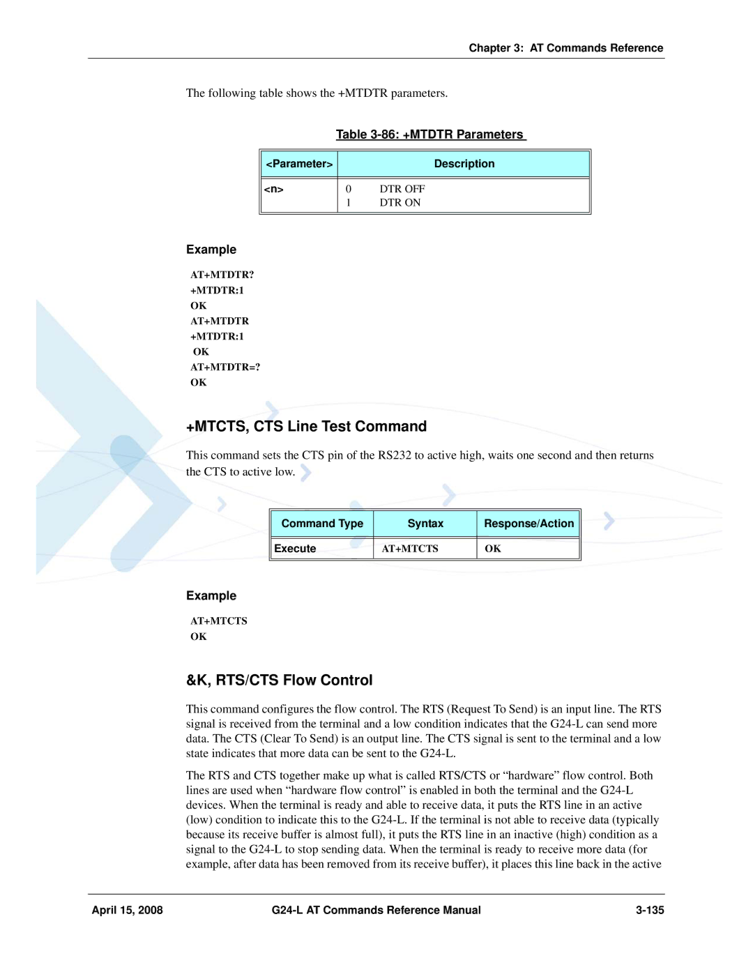
+MTDTR, DTR Line Test Command
RTS/CTS Flow Control
+MTCTS, CTS Line Test Command
Command Type Syntax Response/Action Execute
April 15 G24-L AT Commands Reference Manual 135
OK AT&K4
Circuit 109 Behavior
87 &K Parameters
AT&K?
OK AT&C0
April 15 G24-L AT Commands Reference Manual 137
88 &C Parameters
AT&C?
OK AT&D1
Circuit 108 Behavior
89 &D Parameters
AT&D?
AT+MCWAKE?
April 15 G24-L AT Commands Reference Manual 139
+MCWAKE, Gprs Coverage
90 +MCWAKE Parameters
AT+ Mggind =?
+MGGIND, GSM/GPRS Service Indicator
91 +MGGIND Parameters
AT+ Mggind ?
Parameter Description Fun
April 15 G24-L AT Commands Reference Manual 141
+CFUN, Shut Down Phone Functionality
92 +CFUN Parameters
+ICF?
+ICF, DTE-DCE Character Framing
93 +ICF Parameters
Parity
+MRST, Perform Hard Reset
ATS97, Antenna Diagnostic
94 ATS97 Parameters
AT+MRST OK
+MIOC, Motorola I/O Configure
+ MIOC?
Parameter Description Pin selection
April 15 G24-L AT Commands Reference Manual 145
95 +MIOC Parameters
Light control example
Data sending vector example
+MIOD, Motorola I/O Define
April 15 G24-L AT Commands Reference Manual 147
+ MIOD?
PIN#
96 +MIOD Parameters
97 Keypad GPIOs
Gpio
+MMAD
April 15 G24-L AT Commands Reference Manual 149
+MMAD, Query and Monitor ADC Value
AT+MMAD=
AT+MMAD=?
AT+MMAD?
98 +MMAD Parameters
AT+MMAD=1
Parameter Description Range/Remark Reportinterv
Average
AT+MMAD =1
+MPCMC, Continuous PCM Clock
April 15 G24-L AT Commands Reference Manual 153
+MPCMC=?
99 +MPCMC Parameters
Parameter Description Flag
+MPCMC?
Basic Audio
General Audio Commands
Audio
Scope
100 Basic and Advanced Audio Modes Comparison
Audio Setup
Advanced Audio Setup
Basic Audio Setup
April 15 G24-L AT Commands Reference Manual 157
+CRSL?
Basic Audio Setup Commands
General Audio Commands
+CRSL, Call Ringer Level
Parameter Description Level
+CLVL, Loudspeaker Volume
April 15 G24-L AT Commands Reference Manual 159
101 +CRSL Parameters
102 +CLVL Parameters
+CMUT, Mute/Unmute Currently Active Microphone Path
103 +CMUT Parameters
104 ATS94 and ATS96 Behavior
Echo Cancel Noise Suppress
April 15 G24-L AT Commands Reference Manual 161
S94, Sidetone Effect
ATS96 ATS94
S96, Echo Canceling
105 S94 Parameters
106 ATS96 and ATS94 Behavior
107 S96 Parameters
Advanced Audio Setup Commands
April 15 G24-L AT Commands Reference Manual 163
+MAPATH, Audio Path
+MAPATH=?
+MAPATH=
+MAPATH?
CRLF+MAPATH2
Parameter Description Direct
Features
April 15 G24-L AT Commands Reference Manual 165
108 +MAPATH Parameters
Output Input
+MAVOL, Volume Setting
Parameter Description Accy
Feature
April 15 G24-L AT Commands Reference Manual 167
109 +MAVOL Parameters
110 Mamut Parameters
+MAMUT, Input Devices Mute
111 Mafeat Parameters
+MAFEAT, Features Selection
Parameter Description Feature
April 15 G24-L AT Commands Reference Manual 169
+MADIGITAL, Analog/Digital Audio Switching
General Audio Commands
112 +MADIGITAL Parameters
April 15 G24-L AT Commands Reference Manual 171
+CALM, Alert Sound Mode
113 +CALM Parameters
114 +MMICG Parameters
+ MMICG, Microphone Gain Value
Parameter Description Gain
Parameter Description RingType
April 15 G24-L AT Commands Reference Manual 173
+CRTT, Ring Type Selection
115 +CRTT Parameters
CRTT=X
116 Ring Tone Types Available
Ring Tone Style Name
+VTD?
April 15 G24-L AT Commands Reference Manual 175
+VTD, Tone Duration
117 +VTD Parameters
+VTS=
+VTS, Command-Specific Tone Duration
118 +VTS Parameters
Dtmf
April 15 G24-L AT Commands Reference Manual 177
Access
Access Control Commands
Repeat Last Command
119 SIM Card Errors
SIM PUK2
120 +CPIN Parameters
SIM PIN
SIM PUK
AT+CPIN? +CPIN SIM PUK2
OK AT+CPIN? +CPIN Ready OK
AT+CPIN? +CPIN SIM PIN
AT+CPIN? +CPIN SIM PUK
Parameter Description Type
+EPIN, Enter SIM PIN2 to Verify PIN2 Indicator
April 15 G24-L AT Commands Reference Manual 181
121 +EPIN Parameters
122 +TPIN Parameters
123 +CPWD Parameters
+CPWD, Change Password
AT+CPWD =?
+CLCK, Facility Lock
OK AT+CPWD?
124 +CLCK Parameters
April 15 G24-L AT Commands Reference Manual 185
AT+CLCK=?
Parameter Description Class
OK AT+CLCK=SC,2 +CLCK OK AT+CLCK=SC,1
+EMPC, Unlocking or Locking Subsidy Code
April 15 G24-L AT Commands Reference Manual 187
Parameter Description Pin
Access Command Type Syntax Response/Action Remarks Set
Reset
125 +EMPC Parameters
AT+EMPC?
April 15 G24-L AT Commands Reference Manual 189
G24-L Response Format
Modem Configuration and Profile
Modem Register Commands
126 Effects of Parameter Settings
Parameter Description Value
April 15 G24-L AT Commands Reference Manual 191
Result Code Suppression
127 V Parameters
128 Qn Parameters
Command Echo
129 En Parameters
ATX?
April 15 G24-L AT Commands Reference Manual 193
Result Code Selection and Call Progress Monitoring Control
130 X Parameters
Bit Map Registers
S14
Description Min Value Max Value Default Value
April 15 G24-L AT Commands Reference Manual 195
S12
Parameter Description Escapecharacter
131 S2 Parameters
+CBAND, Change Radio Band
\G, Software Control
\J, Terminal Auto Rate
\N, Link Type
AT?
?, Return the Value of the Last Updated S-register
Set to Factory Defined Configuration
133 &F Parameters
134 Z Parameters
Sleep Mode Commands
Reset to Default Configuration
April 15 G24-L AT Commands Reference Manual 199
Sleep Mode HW Signals
Sleep Mode AT Commands
10 Wake up Outline
Wakeup-In Line
11 Sleep Mode when S24
April 15 G24-L AT Commands Reference Manual 203
S102, Set Delay Before Sending Data to the Terminal
135 S24 Parameters
136 S102 Parameters
S100, Set Minimum Time for Terminal to Fall into Sleep Mode
Parameter Description Remarks Delta
+MSCTS, Enable/Disable CTS During Wakeup Period
137 Command parameters
April 15 G24-L AT Commands Reference Manual 205
Parameter Description Control
Error Handling Commands
+CMEE, Report Mobile Equipment Error
138 +MSCTS Parameters
AT+CMEE=?
April 15 G24-L AT Commands Reference Manual 207
139 +CMEE Parameters
AT+CMEE?
Parameter Description Err
140 +CME Errors
April 15 G24-L AT Commands Reference Manual 209
141 +CMS Errors
AT+VTD +CME Error AT+CMEE=2
142 +STK Errors
April 15 G24-L AT Commands Reference Manual 211
AT+VTD Error AT+CMEE=1
AT+VTD
AT+CEER?
+CEER, Extended Error Report
April 15 G24-L AT Commands Reference Manual 213
AT+CEER
143 +CEER Parameters
Parameter Description Report
April 15 G24-L AT Commands Reference Manual 215
OK AT+CEER? +CEER2
+CRSM
+CRSM, Restricted SIM Access
UI User Interface
UI User Interface
Fileid
Parameter Description Command
April 15 G24-L AT Commands Reference Manual 217
144 +CRSM Parameters
Parameter Description P1,P2
P2 Mode
Sw1 Sw2 Description
Sw1 Sw2 Error Description
April 15 G24-L AT Commands Reference Manual 219
Parameter Description Sw1 sw2
+CRSM 144,0, Ffffffffff
Parameter Description Sw1 Sw2 Error Description
Stored Profile
View Configuration
April 15 G24-L AT Commands Reference Manual 221
Active Profile
145 &W Parameters
Store User Profile
146 Profile Parameters
AT&K
April 15 G24-L AT Commands Reference Manual 223
AT&C
AT&D
147 &Y Parameters
Default User Profile
AT&Y0 AT&Y1
+CLAN, ME Language
+CMER, Mobile Equipment Event Reporting
148 +CMER Parameters
AT+CLAN=?
149 +CLAN Parameters
Code Description
AT+CLAN?
150 +CIND Parameters
+CIND, Indicator Control
228
151 +CIEV Parameters
+CIEV, Indicator Event Reporting
Unsolicited UI Status Messages
Unsolicited Report
Gprs Functionality
Gprs Commands
Gprs
+CGCLASS, Gprs Mobile Station Class
April 15 G24-L AT Commands Reference Manual 231
152 +CGCLASS Parameters
AT+CGDCONT=?
+CGDCONT, Define PDP Context
AT+CGDCONT?
LF+CGDCONT
153 +CGDCONT Parameters
+CGQMIN, Quality of Service Profile Min Acceptable
154 +CGQMIN Parameters
AT+CGQREQ?
+CGQREQ, Quality of Service Profile Requested
AT+CGQREQ=?
+CGATT, Gprs Attach or Detach
April 15 G24-L AT Commands Reference Manual 237
155 +CGQREQ Parameters
156 +CGATT Parameters
+CGPADDR, Show PDP Address
CRLF+CGPADDR
April 15 G24-L AT Commands Reference Manual 239
157 +CGADDR Parameters
PDPaddress
AT+MGEER?
+MGEER, Gprs Extended Error Report
AT+MGEER=?
158 +MGEER Parameters
April 15 G24-L AT Commands Reference Manual 241
ATD*GPRSSC Connect
99, Request Gprs Service D
Gprssc
Gprs Service Code Calledaddres
April 15 G24-L AT Commands Reference Manual 243
159 D*99 Parameters
160 +CGPRS Parameters
+CGPRS, Gprs Coverage
+CGACT, PDP Context Activate or Deactivate
April 15 G24-L AT Commands Reference Manual 245
161 +CGACT Parameters
13 SIM Toolkit
AT+CGACT=1 Error
+MTKR, Profile Download
STK Mechanisms
162 STK Mechanisms
Bit Description
163 +MTKR Parameters
164 Profile Structure Byte 1 Download
Parameter Description Profile
165 Profile Structure Byte 2 Other
April 15 G24-L AT Commands Reference Manual 249
166 Profile Structure Byte 3 Proactive SIM
168 Profile Structure Byte 5 Event driven information
167 Profile Structure Byte 4 Proactive SIM
171 Profile Structure Byte 8 Proactive SIM
April 15 G24-L AT Commands Reference Manual 251
173 Profile Structure Byte 10 Soft keys support
172 Profile Structure Byte 9 Proactive SIM
174 Profile Structure Byte 11 Soft keys information
April 15 G24-L AT Commands Reference Manual 253
177 Profile Structure Byte 14 Screen height
178 Profile Structure Byte 15 Screen width
April 15 G24-L AT Commands Reference Manual 255
179 Profile Structure Byte 16 Screen effects
181 Profile Structure Byte 18 Reserved
April 15 G24-L AT Commands Reference Manual 257
+MTKE, Motorola ToolKit Enable
183 +MTKE Parameters
184 +MTKP Field Descriptions
+MTKP, Motorola ToolKit Proactive Unsolicited Indication
Cmd Type Description Responses
185 +MTKP Parameters of Mtkp Field Description
URL
April 15 G24-L AT Commands Reference Manual 261
186 +MTKP Set Command Parameters
+MTKP?
April 15 G24-L AT Commands Reference Manual 263
Command Type Syntax Response/Action Remarks
Command Type Syntax Response/Action Remarks Unsolicited
Additional
April 15 G24-L AT Commands Reference Manual 265
187 +MTKP Parameters Response Code
Parameter Description Result
Event
188 Current Event Types
+MTKP=?
189 Set Event List Parameters
April 15 G24-L AT Commands Reference Manual 267
Code Language
190 Sample Language Codes
April 15 G24-L AT Commands Reference Manual 269
Latin
April 15 G24-L AT Commands Reference Manual 271
AT+MTKM
+MTKM, Motorola ToolKit Menu
191 +MTKM Parameters
ItemId
192 +MTKM Unsolicited Identification Parameters
+MTKM, Motorola ToolKit Menu Response
Parameter Description CCResult
+MTKC, Motorola ToolKit Call Control
+MTKA, Motorola Toolkit Acknowledge
193 +MTKC Parameters
AT+MTKA=1
April 15 G24-L AT Commands Reference Manual 275
194 +MTKA Parameters
OK AT+MTKA? +MTKA
+MIPCALL=?
+MIPCALL, Create a Wireless Link
+MIPCALL
+MIPCALL?
195 +MIPCALL Parameters
+MIPOPEN, Open a Socket UDP or TCP
APN
196 +MIPOPEN Parameters
AT+MIPOPEN
+MIPODM, Open a Socket UDP or TCP in Online Data Mode
April 15 G24-L AT Commands Reference Manual 279
Error AT+MIPOPEN?
AT+MIPODM=?
AT+MIPODM=
AT+MIPODM?
+MIPODM 0,0
Remote Port
April 15 G24-L AT Commands Reference Manual 281
197 +MIPODM Parameters
Remote IP
Numberofacknowledgedbytes
+MIPCLOSE, Close a Socket
198 +MIPCLOSE Parameters
Parameter Description SocketID
Parameter Description Size
April 15 G24-L AT Commands Reference Manual 283
+MIPSETS, Set Size for Automatic Push
199 +MIPSETS Parameters
200 +MIPSEND Parameters
+MIPSEND, Send Data
Free Size
+MIPPUSH, Push Data into Protocol Stack
April 15 G24-L AT Commands Reference Manual 285
Destination IP
+MIPFLUSH, Flush Data from Buffers
201 +MIPPUSH Parameters
202 +MIPFLUSH Parameters
203 +MIPRUDP Parameters
Set Command Event
+MIPRUDP, Receive Data from UDP Protocol Stack
+MIPRTCP, Receive Data from TCP Protocol Stack
Syntax
+MIPSTAT, Status Report
MIPXOFF, Flow Control Xoff
204 +MIPRTCP Parameters
Event
Mipconf Configure Internal TCP/IP stack
April 15 G24-L AT Commands Reference Manual 289
MIPXON, Flow Control Xon
MinTO
206 +MIPCONF Parameters
Parameter Description Socket
Retrnum
April 15 G24-L AT Commands Reference Manual 291
Parameter Description Maxclosedelay
Isnackindreq
TOS
+MPING, Start Ping Execution Icmp Protocol
+MPING
Count
207 +MPING Command Parameters
April 15 G24-L AT Commands Reference Manual 293
Destination IP/hostname
TTL
TimeOut
TOS
RTT
April 15 G24-L AT Commands Reference Manual 295
208 +MPING Unsolicited Response Parameters
Parameter Description Destination IP
+MPINGSTAT
+MPINGSTAT, Status Update for +MPING Execution
ReceivedMessages
April 15 G24-L AT Commands Reference Manual 297
209 +MPINGSTAT Unsolicited Response Parameters
SentMessages
298
Primary DNS server IP, Secondary
April 15 G24-L AT Commands Reference Manual 299
+MSDNS, Set DNS IP Address
210 +MSDNS Parameters
OK AT+MSDNS?
IP Cidr
Listen Mode
April 15 G24-L AT Commands Reference Manual 301
White List
+MIPCFF
211 +MIPCFF Parameters
Parameter Description Value Socketid
AT+MIPCFF?
Parameter Description Value Error Codes
212 Filtering Error Codes and Status
April 15 G24-L AT Commands Reference Manual 303
NOP Compatible
Ignored Compatible Only Commands
Command Description
NOP Compatible
Phone State Transactions
Setting Up the G24-L Power On and Initial Actions
Detailed Phone State Transactions
Setting Up the G24-L Power On and Initial Actions
Recommended G24-L Initialization Workflow
Recommended G24-L Initialization after Powerup
Recommended G24-L Initialization after Powerup
RS232 Lines Setup
Test G24-L Communication
Basic Configuration
ATE1
Baud setting example
SIM Card Status
SIM Card Status
G24-L Network Connection
G24-L Network Connection
Terminal Synchronization
Terminal Synchronization
Managing Stored Messages in the G24-L Memory
AT+CMGD=4
Setting Text Mode Parameters Using AT+CMGW and AT+CMGS
AT+CNMI=,1
AT+CMGR=4
AT+CMSS=143
AT+CMGW
AT+CMGR=179
Sending Messages Using AT+CMGS
Deleting Messages Using AT+CMGD
AT+CMGD=179
No Carrier AT+CHLD=0
Dialing Using ATD
AT+FCLASS=1
AT+CPBS? +CPBS MT
Direct Dialing from Phone Book
Call Forwarding
Dialing the Last Number Example
Voice Call Manipulations
Call Waiting
Conference Call
Data Call
Switching Modes Data Mode/Command Mode
Data Call
AT+CGATT=1
Establishing Gprs PDP Context
Activating a Saved Profile in G24-L
Two Ways to Activate PDP Context
Using the ATD* Command Set
Changing the Character Set
Following is an Ascii translation of the SM contents
Sleep Mode
Sleep Mode
Example of G24-L Entering Sleep Mode
Example of Terminal Wake G24-L Sleep Mode
Get Inkey
Display Text/Display Idle Mode Text
Play Tone
Get Input
STK
Select Item
Set Up Menu
Send SMS
+MTKM 1,2,OVER the WORLD,1
Set Up Call
Call Control
+MTKM Weather
Launch Browser
Send Dtmf
+MTKM 2,2,IN the COUNTRY,0 AT+MTKM=1,1
23 Setup Event List
Setup Event List
Multi-point Data Transfer Example
TCP Data Transfer Example
TCP/IP
Xoff and Xon Example
OK +MIPOPEN1,1
Error in Reopening a Valid Socket
Handset Mode
Scenarios for Setting Up Handset Mode or Handsfree Mode
Handsfree Mode
Tools Overview
Tools
Tools Overview G24-L AT Commands Reference Manual April 15
Table A-1 AT Commands Alphabetical Description
AT Commands Alphabetical Summary
AT Commands Alphabetical Summary
AT Command Description
Table A-1 AT Commands Alphabetical
Appendix a Reference Tables
+CCLK
+CGPRS
+CMER
+CLCC
+CMT
+CPMS
+CRSM
+EMPC
+MBC
+MIPCFF
+MIPSTAT
+MSCTS
+VTS
S96
S102
S24
S94
Character Set Table CS1 GSM UCS-2
0x17
0x14
0x15
0x16
0x38
0x35
0x36
0x37
0x59
0x56
0x57
0x58
Character Set Table CS3 UCS-2 UTF-8
Character Set Table CS2 Ascii UTF-8
Character Set Table CS6 UCS-2 Full table
Character Set Table CS7 Ascii table
027
024
025
026
055
052
053
054
089
086
087
088
124
118
120
122
AbbreviationFull Name
April 15 G24-L AT Commands Reference Manual Acr & Abbr-1
Abbreviation Full Name
Acr & Abbr-2 G24-L AT Commands Reference Manual April 15
Acronyms and Abbreviations
April 15 G24-L AT Commands Reference Manual Acr & Abbr-3
OEM PCB P PCM PDN PDU PID PPP
Acr & Abbr-4 G24-L AT Commands Reference Manual April 15
RTS RXD
April 15 G24-L AT Commands Reference Manual Acr & Abbr-5
TBD
Index
April 15 G24-L AT Commands Reference Manual Index-1
Mode
Index-2 G24-L AT Commands Reference Manual April 15
TCP/IP
April 15 G24-L AT Commands Reference Manual Index-3
Echo
Index-4 G24-L AT Commands Reference Manual April 15
Status
April 15 G24-L AT Commands Reference Manual Index-5
Close Open
Index-6 G24-L AT Commands Reference Manual April 15
April 15 G24-L AT Commands Reference Manual Index-7
Page
Page
@6802983C95@