ProSecure Unified Threat Management UTM Appliance
ProSecure Product Updates ProSecure Forum Revision History
Support
Trademarks
ProSecure Unified Threat Management UTM Appliance
Settings and Technical Specifications
Updated Features That Reduce Traffic and Features That
Application control see Configure Application Control
Configure Quarantine Settings, Query and Manage
Configure Distributed Spam Analysis section
Appendix B, Wireless Network Module for the UTM9S UTM25S
Added the Requirements for Entering IP Addresses
Contents
Manually Configure Internet and WAN Settings
Firewall Protection
Content Filtering and Optimizing Scans
Virtual Private Networking Using SSL Connections
Network and System Management
Troubleshoot and Use Online Support
Appendix a xDSL Network Module for the UTM9S and UTM25S
Appendix E ReadyNAS Integration
Appendix H Default Settings and Technical Specifications
Introduction
Key Features and Capabilities
Introduction
Single or multiple exposed hosts Virtual private networks
DSL Features
Wireless Features
Advanced VPN Support for Both IPSec and SSL
Powerful, True Firewall
Stream Scanning for Content Filtering
Security Features
Autosensing Ethernet Connections with Auto Uplink
Easy Installation and Management
Extensive Protocol Support
Model Comparison
Maintenance and Support
UTM model comparison
Service Registration Card with License Keys
Network Modules and Broadband Adapters
Package Contents
Hardware Features
Power LED
Front Panel UTM5 and UTM10
USB port Left LAN LEDs
Test LED Right WAN LED Right LAN LEDs
Front Panel UTM25
Front Panel UTM50
USB port Left LAN LEDs Left WAN LEDs Active
Test LED Right LAN LEDs Right WAN LEDs LEDs
Power LED Left LAN LEDs Left WAN LEDs USB port
Front Panel UTM150
LEDs Right WAN LEDs Test LED Right LAN LEDs
Active WAN LEDs Test LED Right LAN LEDs Right WAN LEDs
Power LED Left WAN LEDs Slot Left LAN LEDs USB port
Front Panel UTM9S and UTM25S and Network Modules
Active WAN LEDs
Test LED Right LAN LEDs
Wireless Network Modules
XDSL Network Modules
LED descriptions UTM5, UTM10, UTM25, UTM50, and UTM150
LED Descriptions, UTM5, UTM10, UTM25, UTM50, and UTM150
Activity Description
DMZ LED
Activity Description LAN ports
WAN ports
LED descriptions UTM9S and UTM25S
LED Descriptions, UTM9S, UTM25S, and their Network Modules
USB LED
Wireless network module
Rear Panel UTM5, UTM10, and UTM25
Receptacle
XDSL network modules
Factory Defaults Security lock
Reset button Receptacle
Rear Panel UTM50 and UTM150
Port
Security lock AC power Receptacle Factory Defaults
Reset button Console switch
Power
Switch
Bottom Panels with Product Labels
ProSecure Unified Threat Management UTM Appliance
ProSecure Unified Threat Management UTM Appliance
Choose a Location for the UTM
Use the Rack-Mounting Kit
Use the Setup Wizard to Provision UTM in Your Network
Steps for Initial Connection
Use the Setup Wizard to Provision the UTM in Your Network
Log In to the UTM
Qualified Web Browsers
Requirements for Entering IP Addresses
ProSecure Unified Threat Management UTM Appliance
Web Management Interface Menu Layout
ProSecure Unified Threat Management UTM Appliance
ProSecure Unified Threat Management UTM Appliance
Use the Setup Wizard to Perform the Initial Configuration
To start the Setup Wizard
Setup Wizard of 10 LAN Settings
Setting Description LAN TCP/IP Setup
Dhcp
Setting Description
DNS Proxy
Setup Wizard of 10 WAN Settings
Setting Description Inter Vlan Routing
Setting Description ISP Login
Setup Wizard WAN Settings screen settings
ISP Type
See Configure Load Balancing Multiple WAN Port Models
Internet IP Address
ISP
Dhcp
Domain Name Server DNS Servers
Setup Wizard of 10 System Date and Time
Get Automatically from ISP radio button
Setup Wizard of 10 Services
Setup Wizard System Date and Time screen settings
Setting Description Set Time, Date, and NTP Servers
For Daylight Savings Time check box
Setup Wizard Services screen settings
Web
Setup Wizard Email Security screen settings
Setup Wizard of 10 Email Security
Setting Description Action
Setup Wizard of 10 Web Security
Scan Exceptions
Http
Setup Wizard of 10 Web Categories to Be Blocked
Setup Wizard Web Categories to be blocked screen settings
Setting Description Blocked Web Categories
Blocked Categories Scheduled Days
Blocked Categories Time of Day
Setup Wizard of 10 Email Notification
Setup Wizard Email Notification screen settings
Setup Wizard Signatures & Engine screen settings
Setup Wizard of 10 Signatures & Engine
Setting Description Update Settings
Setting Description Update Frequency
Setup Wizard of 10 Saving the Configuration
Https Proxy Settings
Register the UTM with Netgear
Use the Web Management Interface to Activate Licenses
ProSecure Unified Threat Management UTM Appliance
To retrieve and display the registered information
Electronic Licensing
Click Retrieve Info
Verify Correct Installation
What to Do Next
Test Connectivity
Test Http Scanning
ProSecure Unified Threat Management UTM Appliance
Manually Configure Internet and WAN Settings
Manually Configure Internet and WAN Settings
Internet and WAN Configuration Tasks
Complete these steps
ProSecure Unified Threat Management UTM Appliance
ProSecure Unified Threat Management UTM Appliance
Connection method Manual data input required
Pptp
If the automatic ISP configuration is successful
Manually Configure the Internet Connection
If the automatic ISP configuration fails
Pptp and PPPoE settings
Balancing Multiple WAN Port Models on page 86 . To use load
DNS server settings
Identifier check box
If the manual ISP configuration is successful
If the manual ISP configuration fails
Configure the WAN Mode
Overview of the WAN Modes
Configure Network Address Translation All Models
Configure Classical Routing All Models
Configure Auto-Rollover Mode
To configure auto-rollover mode
Configure the Failure Detection Method
To configure the failure detection method
Failure detection method settings
Setting Description WAN Failure Detection Method
Ping
Configure Load Balancing Multiple WAN Port Models
To configure load balancing
Configure Protocol Binding Optional
Screen see Outbound Rules Service Blocking on
Add Protocol Binding screen settings
Change Group Names in the Network Database on
Configure Secondary WAN Addresses
To edit a protocol binding
To add a secondary WAN address to a WAN interface
Configure Dynamic DNS
To delete one or more secondary addresses
To configure Ddns
Click Apply to save your configuration
DNS service settings
Set the UTM’s MAC Address and Configure Advanced WAN Options
Advanced WAN settings
Setting Description MTU Size
Setting Speed Description
Upload/Download Settings
1000BaseT FullDuplex. Gigabit Ethernet Router’s MAC Address
Failure Detection Method
Additional WAN-Related Configuration Tasks
LAN Configuration
Manage Virtual LANs and Dhcp Options
LAN Configuration
Port-Based VLANs
Assign and Manage Vlan Profiles
100
Vlan Dhcp Options
101
Dhcp Server
Dhcp Relay
DNS Proxy
102
Configure a Vlan Profile
Ldap Server
To add or edit a Vlan profile
103
104
Edit Vlan Profile screen settings
Setting Description Vlan Profile
105
Port Membership
106
107
Configure Vlan MAC Addresses and Advanced LAN Settings
To enable, disable, or delete one or more Vlan profiles
To configure a Vlan to have a unique MAC address
To edit a Vlan profile
Configure Multihome LAN IP Addresses on the Default
109
To add a secondary LAN IP address
110
Manage Groups and Hosts LAN Groups
To edit a secondary LAN IP address
To delete one or more secondary LAN IP addresses
111
Manage the Network Database
112
113
Known PCs and devices settings
Setting Description Name
Add Computers or Devices to the Network Database
Modify Computers or Devices in the Network Database
Change Group Names in the Network Database
Delete Computers or Devices from the Network Database
To edit the names of any of the eight available groups
115
Set Up Address Reservation
116
To enable and configure the DMZ port
Configure and Enable the DMZ Port
117
Setting Description DMZ Port Setup
DMZ Setup screen settings
118
119
120
Configure Static Routes
Manage Routing
To add a static route to the Static Route table
121
Add Static Route screen settings
122
Configure Routing Information Protocol
To enable and configure RIP Select Network Config Routing
To edit a static route that is in the Static Routes table
To delete one or more routes
RIP Configuration screen settings
124
Authentication for RIP-2B/2M
125
Static Route Example
126
About Firewall Protection
127
Firewall Protection
Administrator Tips
128
Number of supported firewall rule configurations
Outbound Rules Service Blocking
129
Setting Description Outbound Rules
Outbound rules overview
130
Block always
131
Groups and Hosts LAN Groups on
Service Profiles on
132
133
Inbound Rules Port Forwarding
NAT IP
134
Setting Description Inbound Rules
135
136
Quality of Service Profiles on
137
Order of Precedence for Rules
138
To change the default outbound policy
Configure LAN WAN Rules
139
Create LAN WAN Outbound Service Rules
To change an existing outbound or inbound service rule
To enable, disable, or delete one or more rules
140
To create an inbound LAN WAN service rule
Create LAN WAN Inbound Service Rules
141
Configure DMZ WAN Rules
142
To delete or disable one or more rules
143
Create DMZ WAN Inbound Service Rules
Create DMZ WAN Outbound Service Rules
144
To create an inbound DMZ WAN service rule
Configure LAN DMZ Rules
145
146
Create LAN DMZ Outbound Service Rules
Create LAN DMZ Inbound Service Rules
To create an outbound LAN DMZ service rule
To create an inbound LAN DMZ service rule
Examples of Firewall Rules
Inbound Rule Examples
LAN WAN Inbound Rule Host a Local Public Web Server
148
149
Netgear UTM
150
To configure the UTM for additional IP addresses
151
LAN WAN or DMZ WAN Inbound Rule Specify an Exposed Host
152
LAN WAN Outbound Rule Block Instant Messenger
Outbound Rule Example
153
Configure Other Firewall Features
Vlan Rules
To create a Vlan rule
154
Add Customized Services on
Add VLAN-VLAN Service screen settings
155
To edit a Vlan rule
To delete or disable one or more Vlan rules
156
Attack Checks screen settings
Setting Description WAN Security Checks
Attack Checks, VPN Pass-through, and Multicast Pass-through
157
Configure Multicast Pass-Through
To configure multicast pass-through
Setting Description LAN Security Checks
158
159
To enable and configure session limits
Session Limit screen settings
Set Session Limits
To delete one or more multicast source addresses
Session Timeout
To enable ALG for SIP and VPN scanning
161
162
Add Customized Services
163
Services screen settings
To add a customized service
164
Create Service Groups
To edit a service
To delete one or more services
To create a service group
To edit a service group
166
To create an IP group
Create IP Groups
167
To delete an IP group
168
To create a QoS profile
Create Quality of Service Profiles
169
Add QoS Profile screen settings
170
Default High Medium High Low
Create Bandwidth Profiles
To edit a QoS profile
To delete one ore more QoS profiles
To add and enable a bandwidth profile
172
Add Bandwidth Profile screen settings
173
Create Traffic Meter Profiles
To edit a bandwidth profile
To delete one or more bandwidth profiles
174
To add a traffic meter profile
175
Add Traffic Meter Profile screen settings
176
Set a Schedule to Block or Allow Specific Traffic
To edit a traffic meter profile
To delete one or more traffic meter profiles
To add a schedule
178
Add Schedule screen settings
Scheduled Days
Enable Source MAC Filtering
Setting Description Scheduled Time of Day
To edit a schedule
To delete one or more schedules
To remove one or more entries from the table
180
To set up IP/MAC bindings
Set Up IP/MAC Bindings
181
IP/MAC Binding screen settings
Setting Description Email IP/MAC Violations
182
IP/MAC Bindings
Configure Port Triggering
To edit an IP/MAC binding
To remove one or more IP/MAC bindings from the table
183
To add a port-triggering rule
Port Triggering screen settings
184
To display the status of the port-triggering rules
To edit a port-triggering rule
185
Configure Universal Plug and Play
186
Enable and Configure the Intrusion Prevention System
To enable intrusion prevention
To configure intrusion prevention
IPS screen settings
Security Category Settings
188
IPS, screen 1 Firewall Protection
189
190
IPS uncommon attack names
Attack Name Description Web
Attack Name Description
191
Misc
About Content Filtering and Scans
192
Default Email and Web Scan Settings
Default email and web scan settings
Content Filtering and Optimizing Scans
193
Configure Email Protection
Customize Email Protocol Scan Settings
To configure the email protocols and ports to scan
Scan type Default scan setting Default action if applicable
Protocol Scan Settings on
195
To configure the antivirus settings for email traffic
Customize Email Antivirus and Notification Settings
196
Anti-Virus screen settings for email traffic
197
Notification Settings
Setting Description Scan Exceptions
198
Email Content Filtering
Setting Description Email Alert Settings
199
SUBJECT%, %FILENAME%, %ACTION%, %VIRUSNAME%
200
Email Filters screen settings
Setting Description Email Filters
Filter by Password-Protected Attachments ZIP, RAR, etc
201
Setting Description Filter by File Type
Protect Against Email Spam
202
Filter by File Name
Set Up the Whitelist and Blacklist
203
To configure the whitelist and blacklist
204
Whitelist/Blacklist screen settings
205
Configure the Real-Time Blacklist
To enable the real-time blacklist
To add a blacklist provider to the real-time blacklist
206
Configure Distributed Spam Analysis
207
Setting Description Distributed Spam Analysis
Distributed Spam Analysis screen settings
208
209
Anti-Spam Engine Settings
Low Medium-Low
Configure Web and Services Protection
Customize Web Protocol Scan Settings
Setting Description Send Quarantine Spam Report
210
To configure the web protocols and ports to scan
211
Configure Https Smart Block
212
Add or Edit Https Smart Block Profile settings
213
214
To change a profile
215
Configure Web Malware or Antivirus Scans
216
Anti-Virus screen settings for HTTP/HTTPS traffic
217
Scan Exception
Html Scan
Configure Web Content Filtering
218
To configure web content filtering
219
220
Setting Description Content Filtering
Content Filtering screen settings
221
222
Full-Text Search
Performance Management on
Block Web Objects
223
Configure Web URL Filtering
Setting Description Web Category Lookup
224
URL
To configure web URL filtering
225
URL Filtering screen settings
Setting Description Whitelist
226
Blacklist
227
URL%
How Https Scanning Works
Configure Https Scanning and SSL Certificates
228
229
Configure the Https Scan Settings
To configure the Https scan settings
Https Settings screen settings
230
Manage SSL Certificates for Https Scanning
231
Manage the Active Https Certificate
232
Manage Trusted Https Certificates
233
Manage Untrusted Https Certificates
Specify Trusted Hosts for Https Scanning
To delete an untrusted certificate
To specify trusted hosts
235
Trusted Hosts screen settings
236
Configure the SSL Settings for Https Scanning
To configure the SSL settings for Https scanning
SSL Settings screen settings
237
Configure FTP Scanning
Customize FTP Antivirus Settings
To configure the antivirus settings for FTP traffic
Anti-Virus screen settings for FTP
Configure FTP Content Filtering
To configure the FTP filters
Setting Description Scan Exception
239
Configure Application Control
240
241
242
243
To select one or more categories of applications
To select one or more individual applications
To search for an application
244
245
Application Control Policy pop-up screen settings
Setting Description Policy for a category of applications
246
Meter Profiles on
To change an existing application control profile
247
To delete one or more application control profiles
Set Exception Rules for Web and Application Access
248
To set web access exception rules
249
Application
250
Https Smart Block
File Extension
251
Add or Edit Exceptions screen settings
URL Filtering
Web Category
252
253
See Configure Radius VLANs on
254
Delete Groups on
Ldap
255
To select a category of applications
To select a single application
To search for an application
For Exceptions for Web and Application Access on
256
To change an existing exception rule
To disable, enable, or delete one or more exception rules
257
To create and manage custom categories
258
Custom categories applications
259
Custom Categories screen settings
260
To select one or more categories of applications
To select one or more individual applications
261
To remove one or more categories or applications from
Applications in this Category table
To add a URL
To configure scanning exclusion rules
Set Scanning Exclusions for IP Addresses and Ports
To change an existing custom category
To delete one or more custom categories
Scanning Exclusion screen settings
263
Virtual Private Networking
264
IP addressing for VPNs in dual WAN port systems
265
Create Gateway-to-Gateway VPN Tunnels with the Wizard
266
267
Setting Default Value IKE policy
268
3DES
SHA-1
IPSec VPN Wizard settings for a gateway-to-gateway tunnel
269
Setting Description Secure Connection Remote Accessibility
270
Create a Client-to-Gateway VPN Tunnel
271
272
IPSec VPN Wizard settings for a client-to-gateway tunnel
Select the VPN Client radio button. The default remote Fqdn
273
Fqdn
274
275
Information required to configure the VPN client
Component Example Information to be collected
276
277
278
VPN client advanced authentication settings
Setting Description Advanced features
279
NAT-T
280
Type vpnclient
To create new authentication settings
281
VPN client authentication settings
282
10.34.116.22
IKE
283
To create an IPSec configuration
Setting Description Local and Remote ID
Type netgearplatform
284
285
VPN client IPSec configuration settings
ESP
To specify the global parameters
286
Test the Netgear VPN Client Connection
287
Click Gateway-Tunnel, and press Ctrl+O
288
View the UTM IPSec VPN Connection Status
Netgear VPN Client Status and Log Information
289
View the UTM IPSec VPN Log
To query the IPSec VPN log
IPSec VPN Connection Status screen information
290
Manage IPSec VPN and IKE Policies
291
To access the IKE Policies screen
Manage IKE Policies
IKE Policies Screen
292
List of IKE Policies table information
293
Manually Add or Edit an IKE Policy
To delete one or more IKE polices
To add an IKE policy manually
294
295
Add IKE Policy screen settings
Setting Description Mode Config Record
296
General
Remote
297
IKE SA Parameters
298
To edit an IKE policy
Setting Description Extended Authentication
299
VPN Policies Screen
Manage VPN Policies
300
List of VPN Policies table information
301
To enable or disable one or more VPN policies
Manually Add or Edit a VPN Policy
To delete one or more VPN polices
To add a VPN policy manually
303
Setting Description General
Add New VPN Policy screen settings
304
Configure Keep-Alives
305
Traffic Selection
Manual Policy Parameters
306
Setting Description Auto Policy Parameters
307
To edit a VPN policy
Configure Extended Authentication Xauth
308
Configure Xauth for VPN Clients
To enable and configure Xauth
Extended authentication settings
309
User Database Configuration
Radius Client and Server Configuration
To configure primary and backup Radius servers
310
Radius Client screen settings
Setting Description Primary Radius Server
Backup Radius Server
Connection Configuration
Assign IP Addresses to Remote Users Mode Config
Mode Config Operation
Configure Mode Config Operation on the UTM
312
To configure Mode Config on the UTM
313
Setting Description Client Pool
Add Mode Config Record screen settings
314
315
Traffic Tunnel Security Level
316
317
318
Setting Description IKE SA Parameters
Select Group 2 1024 bit
User Database Configuration on
Configure the ProSafe VPN Client for Mode Config Operation
319
320
Type GWModeConfig
321
VPN client authentication settings Mode Config
322
VPN client advanced authentication settings Mode Config
Type TunnelModeConfig
323
324
VPN client IPSec configuration settings Mode Config
Enter
Configure the Mode Config Global Parameters
325
Test the Mode Config Connection
326
Modify or Delete a Mode Config Record
To edit a Mode Config record
To delete one or more Mode Config records
327
Configure Keep-Alives
Configure Keep-Alives and Dead Peer Detection
328
Configure Dead Peer Detection
To configure DPD on a configured IKE policy
Keep-alive settings
329
Configure NetBIOS Bridging with IPSec VPN
To enable NetBIOS bridging on a configured VPN tunnel
Dead Peer Detection settings
330
Configure the Pptp Server
331
Setting Description Pptp Server
Pptp Server screen settings
332
Setting Description Authentication
View the Active Pptp Users
To view the active Pptp tunnel users
333
Configure the L2TP Server
Pptp Active Users screen information
334
Pptp IP
Setting Description L2TP Server
L2TP Server screen settings
335
For More IPSec VPN Information
View the Active L2TP Users
To view the active L2TP tunnel users
L2TP Active Users screen information
SSL VPN Portal Options
337
Build a Portal Using the SSL VPN Wizard
Virtual Private Networking Using SSL Connections
To start the SSL VPN Wizard
338
SSL VPN Wizard of 6 Portal Settings
339
Setting Description Portal Layout and Theme Name
SSL VPN Wizard of 6 screen settings portal settings
340
341
SSL VPN Portal Pages to Display
Wizard of 6 Client IP Addresses and Routes on
6 Port Forwarding on
SSL VPN Wizard of 6 Domain Settings
342
SSL VPN Wizard of 6 screen settings domain settings
Server Configuration
343
Radius Client
344
345
Windows login account name in email format. For
Display name in the dn format. For example
346
SSL VPN Wizard of 6 screen settings user settings
SSL VPN Wizard of 6 User Settings
347
SSL VPN Wizard of 6 Client IP Addresses and Routes
348
349
Setting Description Client IP Address Range
Add Routes for VPN Tunnel Clients
SSL VPN Wizard of 6 Port Forwarding
Setting Description Add New Application for Port Forwarding
350
SSL VPN Wizard of 6 Verify and Save Your Settings
351
SSH
Add New Host Name for Port Forwarding
352
Access the New SSL VPN Portal
353
354
355
View the UTM SSL VPN Connection Status
356
Manually Configure and Modify SSL Portals
View the UTM SSL VPN Log
To query the SSL VPN log
357
358
To create an SSL VPN portal layout
Manually Create or Modify the Portal Layout
359
360
Add Portal Layout screen settings
361
Configure Domains, Groups, and Users
Setting Description SSL VPN Portal Pages to Display
To edit a portal layout
To delete one or more portal layouts
Configure Applications for Port Forwarding
Add Servers and Port Numbers
To add a server and a port number
363
To add servers and host names for client name resolution
Add a Host Name
364
TCP application Port number
Fully Qualified Domain Name. The full server name
Configure the SSL VPN Client
365
Configure the Client IP Address Range
SSL VPN Client screen settings
To define the client IP address range
366
To add an SSL VPN tunnel client route
Add Routes for VPN Tunnel Clients
367
To change the LCP time-out
Configure the Advanced SSL VPN Client Settings
368
Use Network Resource Objects to Simplify Policies
Add New Network Resources
To define a network resource
369
Resources screen settings to edit a resource
Edit Network Resources to Specify Addresses
To delete one or more network resources
To edit network resources
Configure User, Group, and Global Policies
371
Global Default Policy
372
View Policies
Add a Policy
To view the existing policies
To add an SSL VPN policy
Add SSL VPN Policy screen settings
Setting Description Policy For
374
Add SSL VPN Policies
375
Resource Objects to Simplify Policies on
To edit an SSL VPN policy
376
To delete one or more SSL VPN policies
For More SSL VPN Information
377
Authentication Process and Options
378
External authentication protocols and methods
Manage Users, Authentication, and VPN Certificates
Authentication Description Protocol or method
379
Configure Authentication Domains, Groups, and Users
Login Portals
Administrative Users and Users with Guest Privileges
380
Users with Special Access Privileges
381
382
383
Active Directories and Ldap Configurations
Unauthenticated or Anonymous Users
How an Active Directory Works
384
How to Bind a DN in an Active Directory Configuration
385
386
Select Users Domains
387
Configure Domains
Create and Delete Domains
To create a domain
388
389
Add Domain screen settings
390
391
392
393
Configure Groups
Edit Domains
To delete one or more domains
To edit a domain
To create a VPN group
Create and Delete Groups
395
Groups screen settings
Edit Groups
To delete one or more groups
To edit a VPN group
To create and manage custom groups
Configure Custom Groups
397
398
Add Custom Group screen settings
399
To delete one or more custom groups
To change an existing custom group
400
To create an individual user account
Configure User Accounts
401
402
Add User screen settings
See Configure Extended Authentication Xauth on
To delete one or more user accounts
403
Set User Login Policies
Configure Login Policies
To configure user login policies
404
To restrict logging in based on IP address
Configure Login Restrictions Based on IP Address
405
Configure Login Restrictions Based on Web Browser
By Source IP Address screen settings
To delete one or more addresses
To restrict logging in based on the user’s browser
To delete one or more browsers
Internet Explorer Opera Netscape Navigator
407
To modify user settings, including passwords
Change Passwords and Other User Settings
408
Edit User screen settings
Configure Extended Authentication Xauth on
DC Agent
409
410
To download ProSecure DC Agent software and add a DC agent
411
To configure AD SSO with a DC agent
DC Agent screen settings
To edit a DC agent
412
413
414
Configure Radius VLANs
To do so, follow this procedure
To configure a Radius Vlan
415
Configure Global User Settings
416
To log out all active users
View and Log Out Active Users
417
To view all or selected users
Active Users screen settings
418
Manage Digital Certificates for VPN Connections
419
VPN Certificates Screen
420
To view and upload trusted certificates
Manage CA Certificates
421
To delete one or more digital certificates
Manage Self-Signed Certificates
422
423
424
Generate self-signed certificate request settings
512 1024 2048
425
Manage the Certificate Revocation List
View and Manage Self-Signed Certificates
To delete one or more SCRs
To delete one or more self-signed certificates
To delete one or more CRLs
427
Bandwidth Capacity
Performance Management
428
Network and System Management
Features That Reduce Traffic
429
430
Content Filtering
431
Source MAC Filtering
Features That Increase Traffic
432
433
Port Triggering
Configure the DMZ Port
434
Configure Exposed Hosts
Configure VPN Tunnels
Use QoS and Bandwidth Assignments to Shift the Traffic Mix
Assign QoS Profiles
Change Passwords and Administrator and Guest Settings
System Management
Monitoring Tools for Traffic Management
436
437
To configure the UTM for remote management
Configure Remote Management Access
438
Https//IPaddress or https//FullyQualifiedDomainName
439
Use a Simple Network Management Protocol Manager
440
441
Global Snmp settings and SNMPv1/v2c settings
Setting Description Snmp Global Settings
SNMPv1/v2c Settings
442
To configure the SNMPv3 settings
SNMPv3 settings
Setting Description SNMPv3 Settings
443
444
Manage the Configuration File
Restore Settings
To edit an SNMPv3 user profile
To delete one or more SNMPv3 user profiles
To back up settings
Back Up Settings
446
Revert to Factory Default Settings
Restore Settings
447
View the Available Firmware Versions
Update the Firmware
448
Firmware screen, available versions
449
Click Install Downloaded Firmware
450
To download the latest firmware for your UTM
451
452
453
Update the Scan Signatures and Scan Engine Firmware
Reboot without Changing the Firmware
To reboot the UTM without changing the firmware
454
455
Configure Date and Time Service
Configure Automatic Update and Frequency Settings
Signatures & Engine screen settings
456
System Date & Time screen settings
Adjust for Daylight Savings Time check box
To set time, date, and NTP servers
457
Connect to a ReadyNAS and Configure Quarantine Settings
458
Log Storage
Connect to a ReadyNAS
To connect to the ReadyNAS on the UTM
459
Configure the Quarantine Settings
To configure the quarantine settings
ReadyNAS Integration screen settings
460
Unauthenticated or Anonymous Users on
Quarantine settings
461
Enable the WAN Traffic Meter
462
Monitor System Access and Performance
463
Setting Description Enable Traffic Meter
464
Traffic Counter
Event Notifications on
Setting Description When Limit is reached
465
Configure Logging, Alerts, and Event Notifications
Configure the Email Notification Server
To configure the email notification server
466
Email Notification screen settings
Configure and Activate System, Email, and Syslog Logs
467
To configure and activate logs
468
Email and Syslog screen settings
Setting Description System Logs Option
Email Logs to Administrator
469
470
Logs screen see Configure and Activate Firewall Logs on
Send Logs via Syslog
How to Send Syslogs over a VPN Tunnel between Sites
Configure Gateway 1 at Site
Setting Description Clear the Following Logs Information
471
Configure Gateway 2 at Site
To change the remote IP address in the VPN policy
To change the local IP address in the VPN policy
472
Configure and Activate Update Failure and Attack Alerts
To configure and activate the email alerts
To specify the syslog server that is connected to Gateway
473
Alerts screen settings
474
TIME%, %PROTOCOL%, %FROM%, %TO%, %SUBJECT%
475
FILENAME%, %ACTION%, %VIRUSNAME%
To configure and activate firewall logs
Configure and Activate Firewall Logs
476
Monitor Real-Time Traffic, Security, and Statistics
Setting Description Routing Logs
477
Dashboard, screen 1
478
To set the poll interval
Dashboard screen threats and traffic information
479
Total Threats
Threats Counts
480
Total Traffic Bytes
Enable and Configure the Intrusion
481
Dashboard screen service statistics information
482
Spam blacklist see Set Up the Whitelist and Blacklist on
Monitor Application Use in Real Time
483
RBL
484
To set the monitoring period
To filter the information that is displayed onscreen
Application Dashboard screen
485
View the System Status
View Status Screens
486
View the System Status Screen
System Status screen fields
487
Status Description
Scan Settings on
View the Network Status Screen
488
System Information
Available Access Points Table
Network Status screen fields
489
LAN Vlan Information
View the Router Statistics Screen
To view the Router Statistics screen
490
Ssid
View the Wireless Statistics Screen UTM9S and UTM25S Only
To view the Wireless Statistics screen
Router Statistics screen fields
491
Wireless Statistics screen fields
492
Radio Statistics Details
AP Statistics
View the Detailed Status Screen
493
494
LAN Port Configuration
Configure and Enable the DMZ Port on
Detailed Status screen fields
495
Settings
MAC Address and Configure
Manually Configure the Internet
496
Access Points Information
Wireless information in SLOT-1 Info or SLOT-2 Info
497
See Configure a Vlan Profile on
Configure a Vlan Profile on
View the Vlan Status Screen
Vlan Status screen fields
View the xDSL Statistics Screen UTM9S and UTM25S Only
View the Active VPN Users
499
View the VPN Tunnel Connection Status
500
View the Active Pptp and L2TP Users
501
View the Port Triggering Status
To view the status of the port-triggering feature
502
Port Triggering Status pop-up screen information
503
View the WAN, xDSL, or USB Port Status
To view the status of a WAN, xDSL, or USB port
Connection Status pop-up screen information
504
View Attached Devices and the Dhcp Leases
View Attached Devices
To view the attached devices in the LAN Groups screen
505
506
Query and Manage the Logs
View the Dhcp Leases
To view the Dhcp leases
507
Overview of the Logs
508
To query and download logs
Query and Download Logs
509
Logs Query screen settings
510
511
512
EMERG, ALERT, CRITICAL, ERROR, WARNING, Notice
Example Use the Logs to Identify Infected Clients
To identify infected clients
513
Log Management
Query and Manage the Quarantine Logs
514
To query the quarantine logs
Query the Quarantined Logs
515
Quarantine screen settings
516
View and Manage the Quarantined Spam Table
517
View and Manage the Quarantined Infected Files Table
518
For an end user to send a spam report
Spam Reports for End Users
519
Click Send Report
View, Schedule, and Generate Reports
520
Enable Application Session Monitoring
521
Report Filtering Options
To configure filtering options
522
Report screen filtering options settings
523
Horizontal Bar
Pie
To display the report templates and view reports onscreen
Use Report Templates and View Reports Onscreen
524
Report screen report template information
525
526
527
IPS & Application
528
Email Activity
Schedule, Email, and Manage Reports
To schedule automatic generation and emailing of reports
529
System
Report screen schedule report settings
Setting Description Schedule Reports
Managing Saved Reports
530
Use Diagnostics Utilities
531
Use the Network Diagnostic Tools
Send a Ping Packet
To send a ping
532
Use the Real-Time Traffic Diagnostics Tool
Trace a Route
Display the Routing Table
Look Up a DNS Address
To use the real-time traffic diagnostics tool
534
Gather Important Log Information
Generate Network Statistics
To gather log information about your UTM
535
Reboot and Shut Down the UTM
Perform Maintenance on the USB Device
536
537
Troubleshoot and Use Online Support
538
Power LED Not On
Basic Functioning
Verify the Correct Sequence of Events at Startup
Test LED Never Turns Off
LAN or WAN Port LEDs Not On
Troubleshoot the Web Management Interface
540
Troubleshoot the ISP Connection
When You Enter a URL or IP Address, a Time-Out Error Occurs
541
To check the WAN IP address
542
Troubleshoot a TCP/IP Network Using a Ping Utility
Test the LAN Path to Your UTM
Ping
543
Ping -n 10 IP address
Test the Path from Your Computer to a Remote Device
544
Restore the Default Configuration and Password
545
Problems with Date and Time
Enable Remote Troubleshooting
Use Online Support
To initiate the support tunnel
To submit a file to Netgear for analysis
Send Suspicious Files to Netgear for Analysis
547
Malware Analysis screen settings
Access the Knowledge Base and Documentation
548
XDSL Network Module for the UTM9S UTM25S
549
XDSL Network Module Configuration Tasks
Configure the xDSL Settings
XDSL Network Module for the UTM9S and UTM25S
550
To configure the xDSL settings
551
Setting Description XDSL Settings
XDSL settings
552
VPI
553
VCI
554
561, and Troubleshoot the ISP Connection on
555
Manually Configure the xDSL Internet Connection
556
557
PPPoE and PPPoA settings
558
559
ATM Ipoa
560
561
Configure Network Address Translation
562
Configure Classical Routing
563
564
565
Configure Load Balancing and Optional Protocol Binding
566
Configure Load Balancing
567
568
569
570
To add a secondary WAN address to the DSL interface
571
572
573
Setting Description SLOT-x Dynamic DNS Status
574
575
Default Address radio button
Advanced DSL settings
576
577
Wireless Network Module for UTM9S and UTM25S
578
Overview of the Wireless Network Module
Configuration Order
Wireless Equipment Placement and Range Guidelines
Wireless Network Module for the UTM9S and UTM25S
To configure the basic radio settings
Configure the Basic Radio Settings
580
581
Radio Settings screen settings
Field Descriptions
582
Operating Frequency Channel Guidelines
583
Wireless Data Security Options
584
Wireless Security Profiles
585
Data encryption
Network authentication
586
Before You Change the SSID, WEP, and WPA Settings
WPA Radius settings
WPA2 Radius settings
587
Configure and Enable Wireless Profiles
To add a wireless profile
Wireless Profiles screen settings
588
Field Description Profile Configuration
Add Wireless Profiles screen settings
589
590
Security Options on
Tkip TKIP+AES
591
WEP Index and Keys
592
Restrict Wireless Access by MAC Address
To edit a wireless profile
To delete one or more wireless profiles
To enable or disable one or more wireless profiles
594
595
Configure a Wireless Distribution System
Access Point Status screen fields
596
Connected Clients
To enable and configure WDS
597
Configure Advanced Radio Settings
To configure WDS on a peer
To configure advanced radio settings
598
Advanced Wireless screen settings
599
Configure WMM QoS Priority Settings
600
601
Test Basic Wireless Connectivity
For More Information About Wireless Configurations
To test for wireless connectivity
602
3G/4G Dongle Configuration Tasks
603
3G/4G Dongles for the UTM9S and UTM25S
Manually Configure the USB Internet Connection
604
To configure the WAN ISP settings for the USB interface
605
USB ISP settings
Setting Description 3G Dongle Details
Connection Settings
606
XDSL, or USB Port Status on
607
To configure the 3G/4G settings
Configure the 3G/4G Settings
608
4G settings
Setting Description 3GStatus
Connection Setting
609
610
APN
611
612
613
614
615
616
617
618
619
Setting Description USB Dynamic DNS Status
620
621
What to Consider Before You Begin
622
Internet
WAN port Physical facility
623
Computer Network Configuration Requirements
Internet Configuration Requirements
Where Do I Get the Internet Configuration Information?
Cabling and Computer Hardware Requirements
Internet Connection Information
625
Overview of the Planning Process
626
Inbound Traffic
627
Inbound Traffic to a Single WAN Port System
Inbound Traffic to a Dual WAN Port System
Inbound Traffic Dual WAN Ports for Improved Reliability
Inbound Traffic Dual WAN Ports for Load Balancing
Virtual Private Networks
629
VPN Road Warrior Client-to-Gateway
630
VPN Road Warrior Single-Gateway WAN Port Reference Case
631
VPN Road Warrior Dual-Gateway WAN Ports for Load Balancing
632
VPN Gateway-to-Gateway
633
634
VPN Telecommuter Single-Gateway WAN Port Reference Case
VPN Telecommuter Client-to-Gateway through a NAT Router
635
636
VPN Telecommuter Dual-Gateway WAN Ports for Load Balancing
637
Supported ReadyNAS Models
638
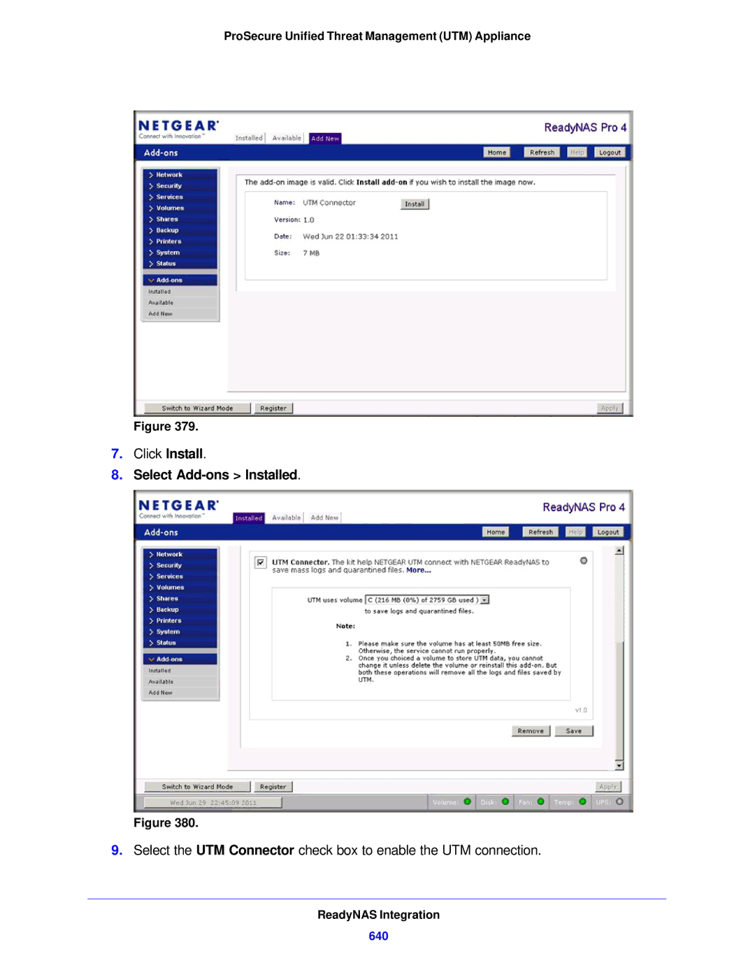
Install the UTM Add-On on the ReadyNAS
To install the UTM add-on on the ReadyNAS
Select Add-ons Add New
ReadyNAS Integration
Select Add-ons Installed
640
Connect to the ReadyNAS on the UTM
641
642
643
What Are the Benefits of Two-Factor Authentication?
Why Do I Need Two-Factor Authentication?
644
Netgear Two-Factor Authentication Solutions
What Is Two-Factor Authentication?
Two-Factor Authentication
To use WiKID for end users
646
647
648
Log message terms
Term Description
Reboot
System Log Messages
System Startup
649
Login/Logout
System logs login/logout
System logs NTP
650
Auto-Rollover Mode
Firewall Restart
IPSec Restart
WAN Status
Load Balancing Mode
System logs WAN status, auto rollover
652
ACTIVEWAN2
System logs WAN status, PPPoE idle timeout
PPP Logs
System logs WAN status, load balancing
653
System logs WAN status, Pptp idle timeout
654
Unicast, Multicast, and Broadcast Logs
Traffic Metering Logs
655
Invalid Packet Logging
Icmp Redirect Logs
Multicast/Broadcast Logs
656
657
Service Logs
Content-Filtering and Security Logs
Service logs
658
Web Filtering and Content-Filtering Logs
659
Spam Logs
Content-filtering and security logs spam
660
Traffic Logs
Malware Logs
Email Filter Logs
661
Content-filtering and security logs IPS
Content-filtering and security logs anomaly behavior
IPS Logs
Anomaly Behavior Logs
Routing Logs
Application Logs
LAN-to-WAN Logs
663
LAN-to-DMZ Logs
DMZ-to-WAN Logs
WAN-to-LAN Logs
664
DMZ-to-LAN Logs
WAN-to-DMZ Logs
Routing logs WAN to DMZ
665
Default Settings
UTM default configuration settings
Feature Login settings Default behavior
666
Default Settings and Technical Specifications
Feature Default behavior WAN connections
Administrative and monitoring settings
667
Feature Default behavior Firewall and network security
668
SIP ALG
IPS
Feature Application security Default behavior
669
Feature Default behavior
670
Radius settings
SSL VPN settings
User, group, and domain settings
671
672
UTM physical and technical specifications
Physical and Technical Specifications
673
UTM IPSec VPN specifications
Feature Specification Major regulatory compliance
Interface specifications
Setting Specification
UTM SSL VPN specifications
Feature Description 802.11b/bg/ng wireless specifications
675
Http//prosecure.netgear.com
676
Feature Description 802.11a/na wireless specifications
AES
FCC Requirements for Operation in the United States
Regulatory Compliance Information
677
European Union
Notification of Compliance Wired
678
679
Additional Copyrights
Terms
680
MD5
Europe EU Declaration of Conformity
Edoc in Languages of the European Community
681
Language Statement
Notification of Compliance Wireless
682
FCC Caution
683
Industry Canada
Important Note Radiation Exposure Statement
Avertissement
684
Interference Reduction Table
685
Index
686
687
688
See also
689
DMZ
690
Blocking 202, 218, 222 setting access exceptions
691
692
Logs 469, 508-510traffic statistics
693
LAN
694
695
696
697
698
699
SSL VPN
700
TCP/IP
701
702
Logs 290, 470
Dhcp 50, 106, 119 ModeConfig
703
704