I/O INTERFACING
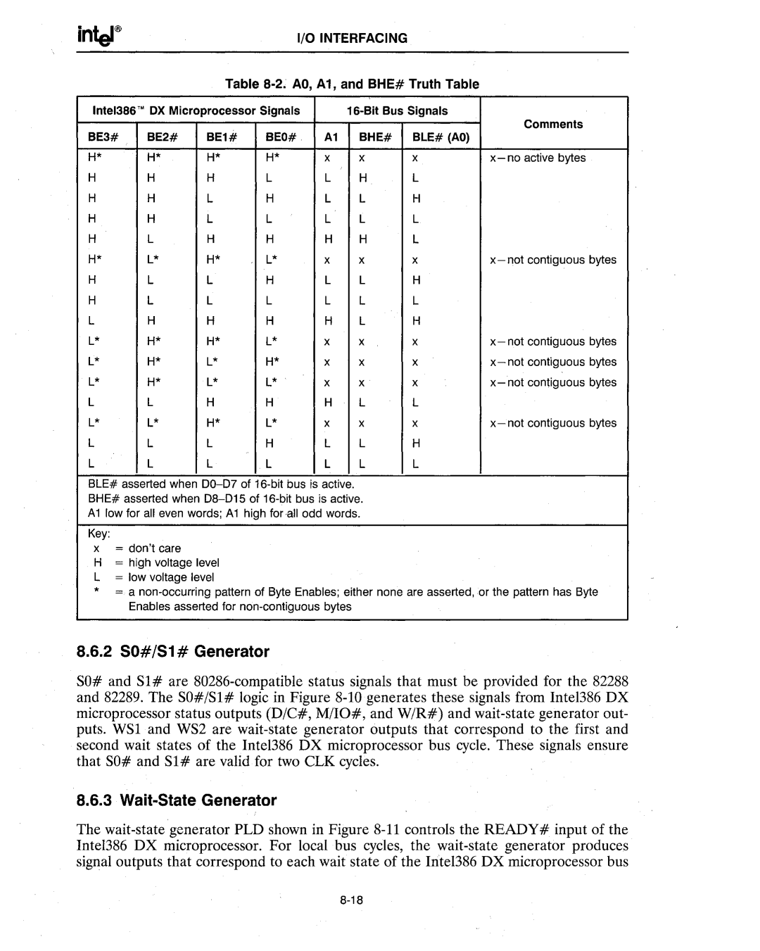
Table 8-2. AD, A1, and BHE# Truth Table
| Inte1386'MOX Microprocessor Signals | | 16-Bit Bus Signals | Comments |
| BE3# | BE2# | BE1# | BEO# | A1 | BHE# | BLE# (AO) |
| |
| H* | H* | H* | H* | x | x | x | x- no active bytes |
| H | H | H | L | L | H | L | |
| H | H | L | H | L | L | H | |
| H | H | L | L | L | L | L | |
| H | L | H | H | H | H | L | |
| H* | L* | H* | L* | x | x | x | x- not contiguous bytes |
| H | L | L | H | L | L | H | |
| H | L | L | L | L | L | L | |
| L | H | H | H | H | L | H | |
| L* | H* | H* | L* | x | x | x | x-not contiguous bytes |
| L* | H* | L* | H* | x | x | x | x-not contiguous bytes |
| L* | H* | L* | L* | x | x | x | x-not contiguous bytes |
| L | L | H | H | H | L | L | |
| L* | L* | H* | L* | x | x | x | x- not contiguous bytes |
| L | L | L | H | L | L | H | |
| L | L | L | L | L | L | L | |
BLE# asserted when 00-07 of 16-bit bus is active.
BHE# asserted when 08-015 of 16-bit bus is active.
A1 low for all even words; A1 high for all odd words.
Key:
x = don'tcare
H= high voltage level L = low voltage level
* = a non-occurring pattern of Byte Enables; either none are asserted, or the pattern has Byte Enables asserted for non-contiguous bytes
8.6.2 SO#/S1 # Generator
SO# and Sl# are 80286-compatible status signals that must be provided for the 82288 and 82289. The SO#/Sl# logic in Figure 8-10 generates these signals from Inte1386 DX microprocessor status outputs (D/C#, M/IO#, and W/R#) and wait-state generator out- puts. WSl and WS2 are wait-state generator outputs that correspond to the first and second wait states of the Intel386 DX microprocessor bus cycle. These signals ensure that SO# and Sl# are valid for two CLK cycles.
8.6.3 Wait-State Generator
The wait-state generator PLD shown in Figure 8-11 controls the READY# input of the Inte1386 DX microprocessor. For local bus cycles, the wait-state generator produces signal outputs that correspond to each wait state of the Intel386 DX microprocessor bus
8-18