PHYSICAL DESIGN AND DEBUGGING
• | "NV'v • | Zo =750 |
| {>- | |
|
| ||||
A | B | (~L=9'~) | C |
| |
| RL |
| Receiver | ||
Driver |
|
|
|
|
|
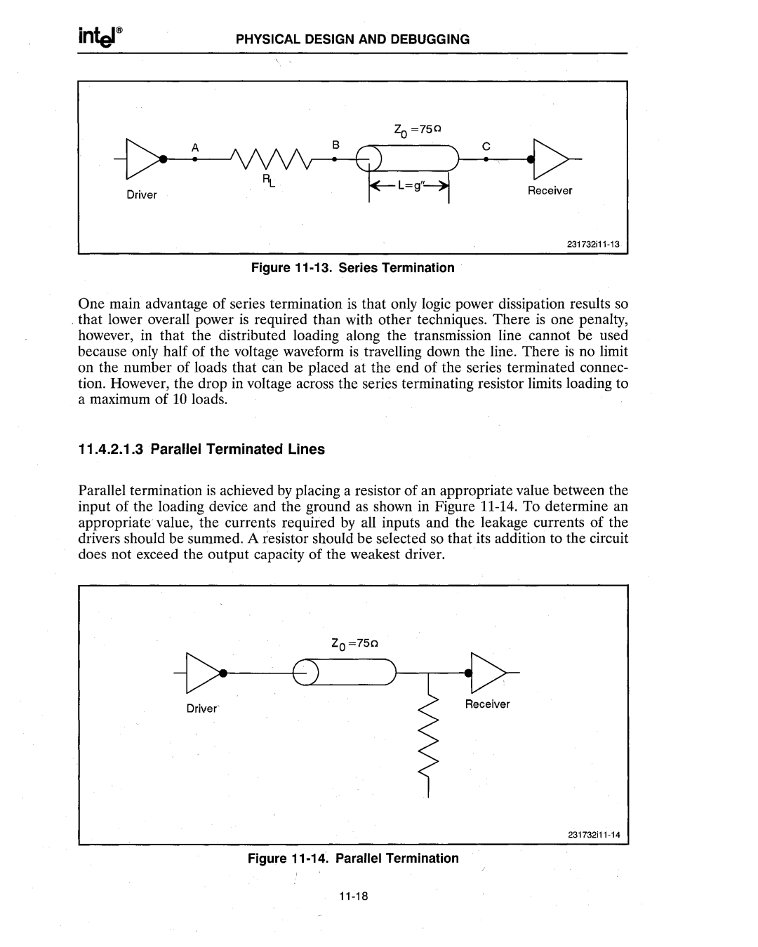
Figure 11 -13. Series Termination
One main advantage of series termination is that only logic power dissipation results so
. that lower overall power is required than with other techniques. There is one penalty, however, in that the distributed loading along the transmission line cannot be used because only half of the voltage waveform is travelling down the line. There is no limit on the number of loads that can be placed at the end of the series terminated connec- tion. However, the drop in voltage across the series terminating resistor limits loading to a maximum of 10 loads.
11.4.2.1.3 Parallel Terminated Lines
Parallel termination is achieved by placing a resistor of an appropriate value between the input of the loading device and the ground as shown in Figure
ZO=750
Driver'
