PHYSICAL DESIGN AND DEBUGGING
B
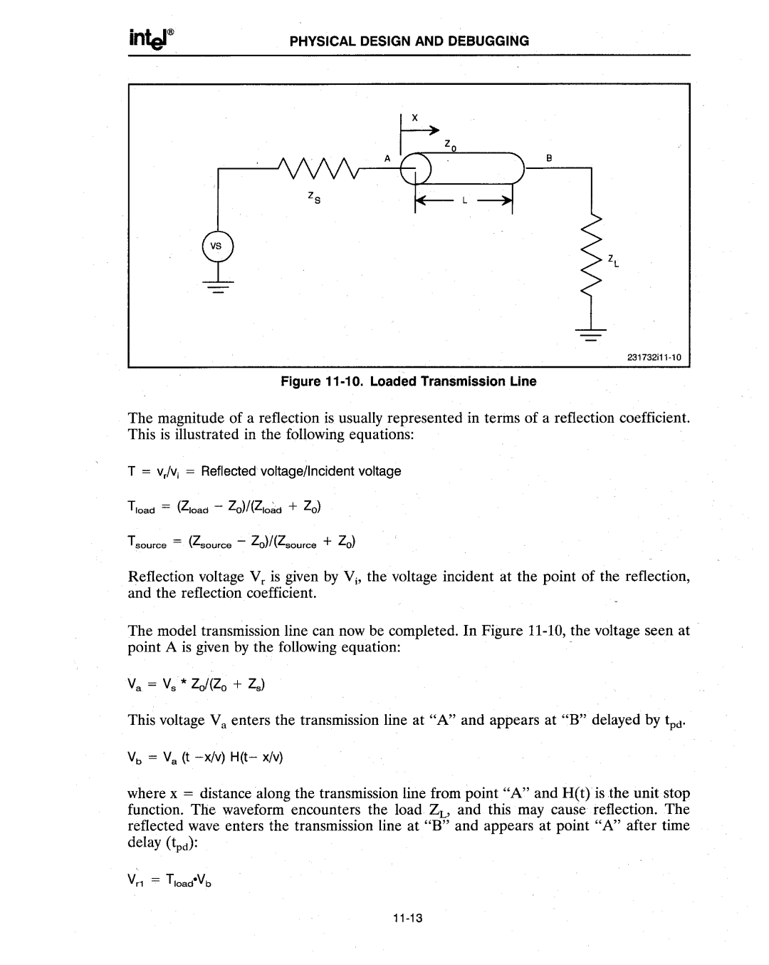
Figure 11-10. Loaded Transmission Line
The magnitude of a reflection is usually represented in terms of a reflection coefficient. This is illustrated in the following equations:
T =. V,lVi = Reflected voltage/Incident voltage
Tsource = (Zsource - Zo)/(Zsource + Zo)
Reflection voltage Vr is given by Vi' the voltage incident at the point of the reflection, and the reflection coefficient.
The model transmission line can now be completed. In Figure
This voltage Va enters the transmission line at "A" and appears at "B" delayed by tpd'
Vb = Va (t
where x = distance along the transmission line from point "A" and H(t)' is the unit stop function. The waveform encounters the load~, and this may cause reflection. The reflected wave enters the transmission line at "B" and appears at point "A" after time delay (~d):