PHYSICAL DESIGN AND DEBUGGING
roo®'
Lo I
rca zo=J~
Co
231732i11-1
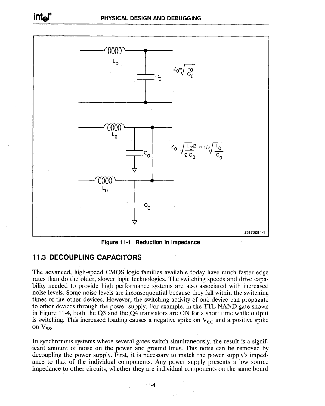
Figure 11-1. Reduction in Impedance
11.3 DECOUPLING CAPACITORS
The advanced, high-speed CMOS logic families available today have much faster edge rates than do the older, slower logic technologies. The switching speeds and drive capa- bility needed to provide high performance systems are also associated with increased noise levels. Some noise levels are inconsequential because they fall within the switching times of the other devices. However, the switching activity of one device can propagate to other devices through the power supply. For example, in the TTL NAND gate shown in Figure 11-4, both the Q3 and the Q4 transistors are ON for a short time while output is switching. This increased loading causes a negative spike on Vee and a positive spike on Vss.
In synchronous systems where several gates switch simultaneously, the result is a signif- icant amount of noise on the power and ground lines. This noise can be removed by decoupling the power supply. First, it is necessary to match the power supply's imped- ance to that of the individual components. Any power supply presents a low source impedance to other circuits, whether they are individual components on the same board
11-4