MULTIBUS I AND Intel386 OX MICROPROCESSOR
| OF | (FROM SLAVE | ||
| INTERRUPT CONTROLLER) | |||
| 8259A | 0, |
| |
| ||||
|
| |||
i: | iT | 74530 CASVALlD(l) |
| |
|
|
|
| |
|
|
| (74500 | 74AlS580 |
|
|
|
| |
'~~
1<
82289
BUS
ARBITER
INTA
MCE
...... | IMBIO'" | vcc':....r: ~~NL | AEN |
LOCALMB ~ | L | ||
"".::: . : . :: .. |
| ||
BUS | - |
|
|
CONTROLLER | WAIT·STATE | 82288 |
- | GENERATOR | BUS |
_ | READY | I ....________~=CO::N=TR=OL:LE:R~.J |
AffDYENI..
ARCY
231732i9·9
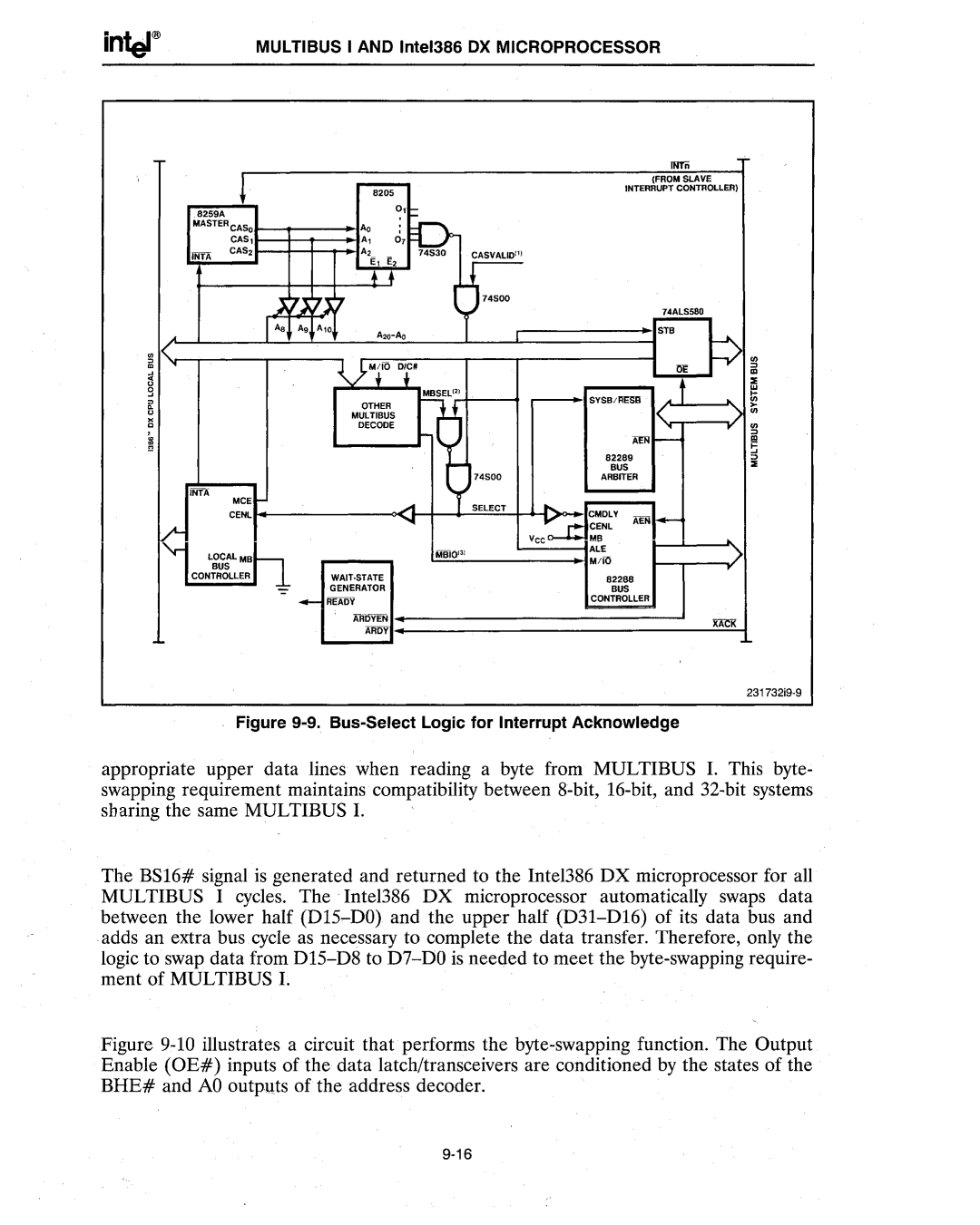
Figure 9-9. Bus-Select Logic for Interrupt Acknowledge
appropriate upper data lines when reading a byte from MULTIBUS 1. This byte- swapping requirement maintains compatibility between
The BSI6# signal is generated and returned to the Intel386 DX microprocessor for all MULTIBUS I cycles. The Intel386 DX microprocessor automatically swaps data between the lower half