PHYSICAL DESIGN AND DEBUGGING
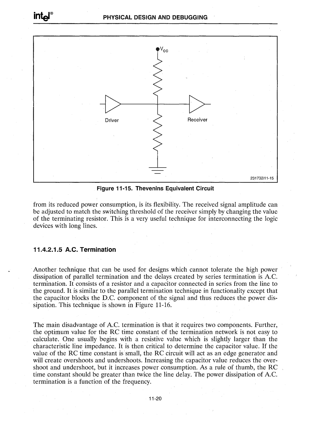
DriverReceiver
Figure 11·15. Thevenins Equivalent Circuit
from its reduced power consumption, is its flexibility. The received signal amplitude can be adjusted to match the switching threshold of the receiver simply by changing the value of the terminating resistor. This is a very useful technique for interconnecting the logic devices with long lines.
11.4.2.1.5A.C. Termination
Another technique that can be used for designs which cannot tolerate the high power dissipation of parallel termination and the delays created by series termination is AC. termination. It consists of a resistor and a capacitor connected in series from the line to the ground. It is similar to the parallel termination technique in functionality except that the capacitor blocks the D.C. component of the signal and thus reduces the power dis- sipation. This technique is shown in Figure
The main disadvantage of AC. termination is that it requires two components. Further, the optimum value for the RC time constant of the termination network is not easy to calculate. One usually begins with a resistive value which is slightly larger than the characteristic line impedance. It is then critical to determine the capacitor value. If the value of the RC time constant is· small, the RC circuit will act as an edge generator. and will create overshoots and undershoots. Increasing the capacitor value reduces the over- shoot and undershoot, but it increases power consumption. As a rule of thumb, the RC time constant should be greater than twice the line delay. The power dissipation of AC. termination is a function of the frequency.