PHYSICAL DESIGN AND DEBUGGING
11.4.2 Impedance Mismatch
As mentioned earlier, the impedance of a transmission line is a function of the geometry of the line, its distance from the ground plane, and the loads along the line. Any discon- tinuity in the impedance will cause reflections.
Impedance mismatch occurs between the transmission line characteristic impedance and the input or output impedances of the devices that are connected to the line. The result is that the signals are reflected back and forth on the line. These reflections can atten- uate or reinforce the signal depending upon the phase relationships. The results of these reflections include overshoot, undershoot, ringing and. other undesirable effects.
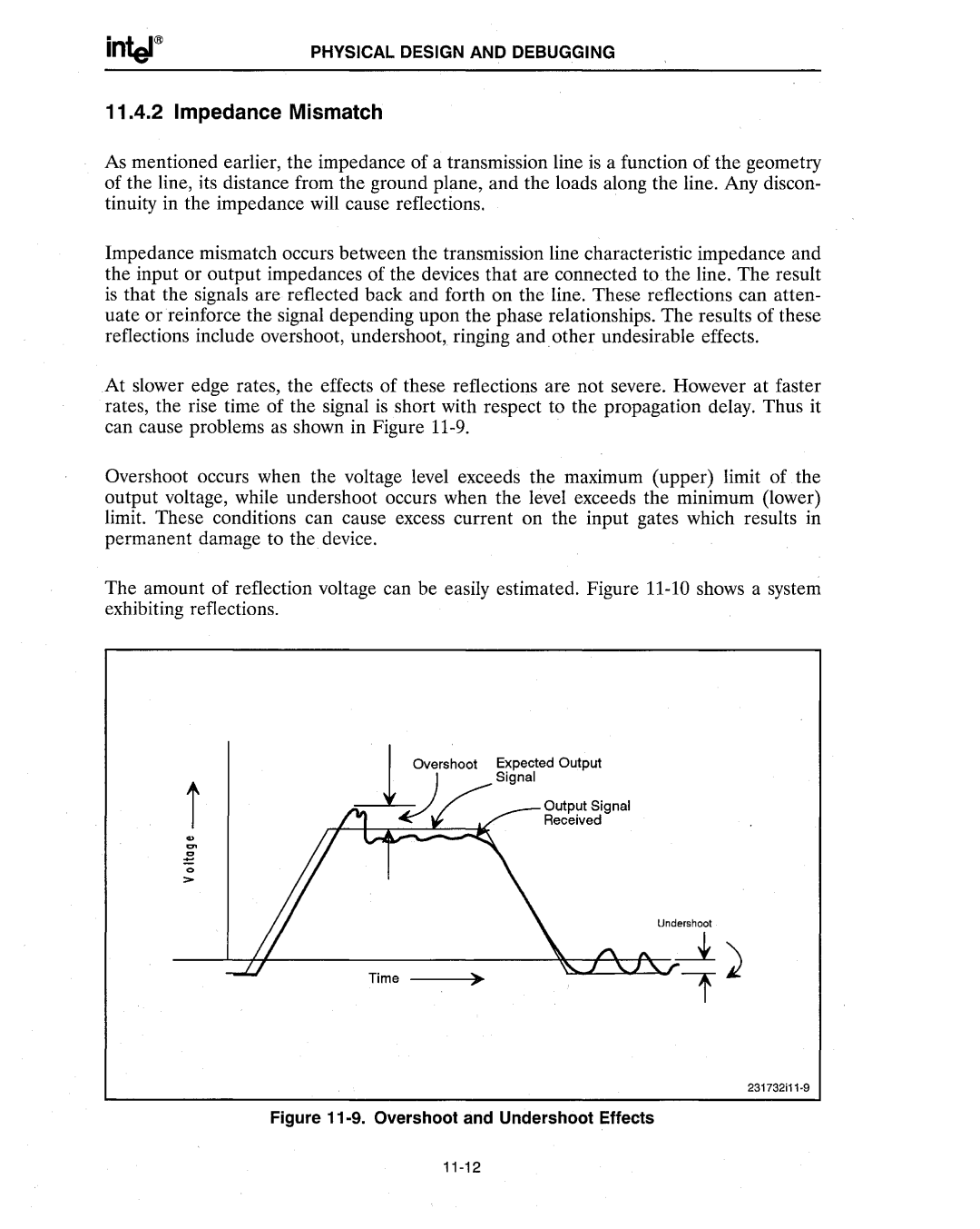
At slower edge rates, the effects of these reflections are not severe. However at faster rates, the rise time of the signal is short with respect to the propagation delay. Thus it can cause problems as shown in Figure
Overshoot occurs when the voltage level exceeds the maximum (upper) limit of the output voltage, while undershoot occurs when the level exceeds the minimum (lower) limit. These conditions can cause excess current on the input gates which results in permanent damage to the device.
The amount of reflection voltage can be easily estimated. Figure
Expected Output
Signal
..
...
~
o
>
Undershoot
