PHYSICAL DESIGN AND DEBUGGING
L=g"
Trace Is Microstrip
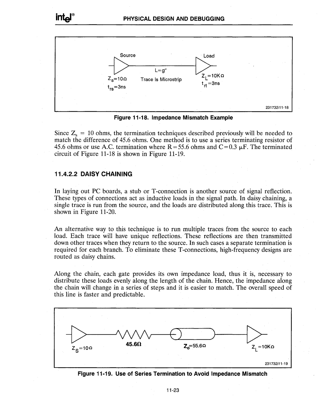
Figure 11-18. Impedance Mismatch Example
Since Zs = 10 ohms, the termination techniques described previously will be needed to match the difference of 45.6 ohms. One method is to use a series terminating resistor of
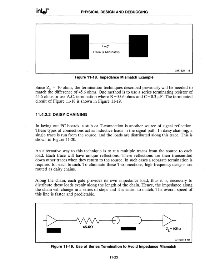
45.6ohms or use A.C. termination where R=55.6 ohms and C=O.3 J.,LF. The terminated circuit of Figure
11.4.2.2 DAISY CHAINING
In laying out PC boards, a stub or
An alternative way to this technique is to run multiple traces from the source to each load. Each trace will have unique reflections. These reflections are then transmitted down other traces when they return to the source. In such cases a separate termination is required for each branch. To eliminate these
Along the chain, each gate provides its own impedance load, thus it is, necessary to distribute these loads evenly along the length of the chain. Hence, the impedance along the chain will change in a series of steps and it is easier to match. The overall speed of this line is faster and predictable.