LOCAL BUS INTERFACE
3.3.2 Crystal Oscillator Clock Generator
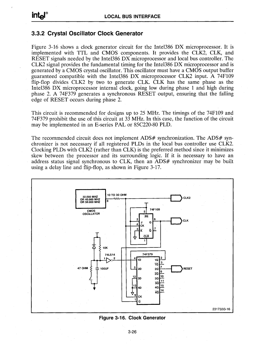
Figure 3-16 shows a clock generator circuit for the Intel386 DX microprocessor. It is implemented with TTL and CMOS components. It provides the CLK2, CLK, and RESET signals needed by the Intel386 DX microprocessor and local bus controller. The CLK2 signal provides the fundamental timing for the Intel386 DX microprocessor and is generated by a CMOS crystal oscillator. This oscillator must have a CMOS output buffer guaranteed compatible with the Inte1386 DX microprocessor CLK2 input. A 74F109 flip-flop divides CLK2 by two to generate CLK. CLK has the same phase as the Intel386 DX microprocessor internal clock, going low during phase 1 and high during phase 2. A 74F379 generates a synchronous RESET output, ensuring that the falling edge of RESET occurs during phase 2.
This circuit is recommended for designs up to 25 MHz. The timings of the 74F109 and 74F379 prohibit the use of this circuit at 33 MHz. In this case, the function of the circuit may be implemented in an E-series PAL or 85C220-80 PLD.
The recommended circuit does not implement ADS# synchronization. The ADS# syn- chronizer is not necessary if all registered PLDs in the local bus controller use CLK2. Clocking PLDs with CLK2 (rather than CLK) is the preferred method since it minimizes skew between the processor and its surrounding logic. If it is necessary to have an address status signal synchronous to CLK, then an ADS# synchronizer may be built using a delay line and flip-flop, as shown in Figure 3-17.
32.000 MHZ | ClK2 | |
OR 40.000 MHZ | ||
8 | ||
OR 50.000 MHZ | ||
| ||
CMOS |
| |
OSCillATOR |
| |
| ClK |
4
5 | 20 |
| RESET | |
12 | 3D | 30 | 10 | |
11 | ||||
|
| _ | ||
13 |
| 30 |
| |
40 | 40 | 15 | ||
|
| 4Q 14 | ||
9 | CK |
|
| |
1 | G |
|
| |
231732i3·16