MEMORY INTERFACING
OE
1/0 PIN
|
| o | Q |
|
| I |
|
|
|
| I ClK |
|
|
|
| I | MACROCEll |
| |
| I |
| ||
| REGISTER |
| ||
INVERT | I |
|
|
|
I |
|
| I | |
CONTROL | I |
|
| |
|
|
| I | |
| I |
|
| |
FEEOBACK |
|
| I | |
I |
| II | ||
|
|
| ||
|
|
| SELECT: | |
IL________________ ~I
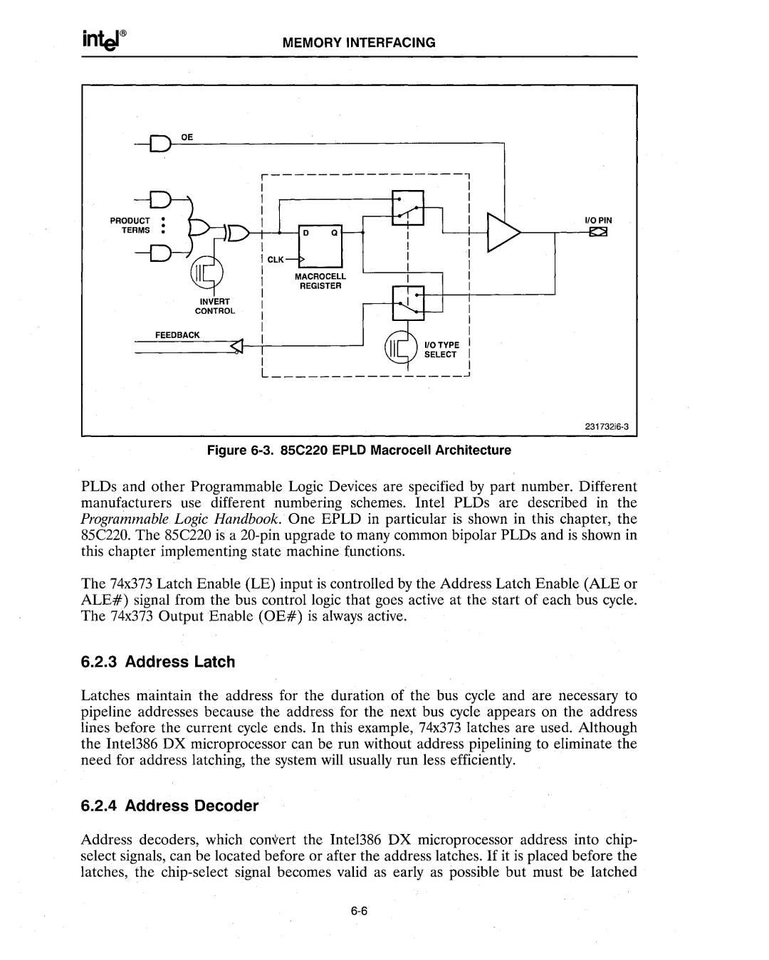
Figure 6-3. 85C220 EPLD Macrocell Architecture
PLDs and other Programmable Logic Devices are specified by part number. Different manufacturers use different numbering schemes. Intel PLDs are described in the Programmable Logic Handbook. One EPLD in particular is shown in this chapter, the 85C220_ The 85C220 is a
The 74x373 Latch Enable (LE) input is controlled by the Address Latch Enable (ALE or ALE#) signal from the bus control logic that goes active at the start of each bus cycle. The 74x373 Output Enable (OE#) is always active.
6.2.3 Address Latch
Latches maintain the address for the duration of the bus cycle and are necessary to pipeline addresses because the address for the next bus cycle appears on the address lines before the current cycle ends. In this example, 74x373 latches are used. Although the Intel386 DX microprocessor can be run without address pipelining to eliminate the need for address latching, the system will usually run less efficiently.
6.2.4 Address Decoder
Address decoders, which convert the Intel386 DX microprocessor address into chip- select signals, can be located before or after the address latches. If it is placed before the latches, the