Intel 386 manual Physical Design and Debugging

Models: 386

1 307
Download 307 pages 15.07 Kb
Page 219
Image 219

PHYSICAL DESIGN AND DEBUGGING

A _ -......--.,---'

3 _ -- + -- _.....

f -----

ey

A4

231732i11-4

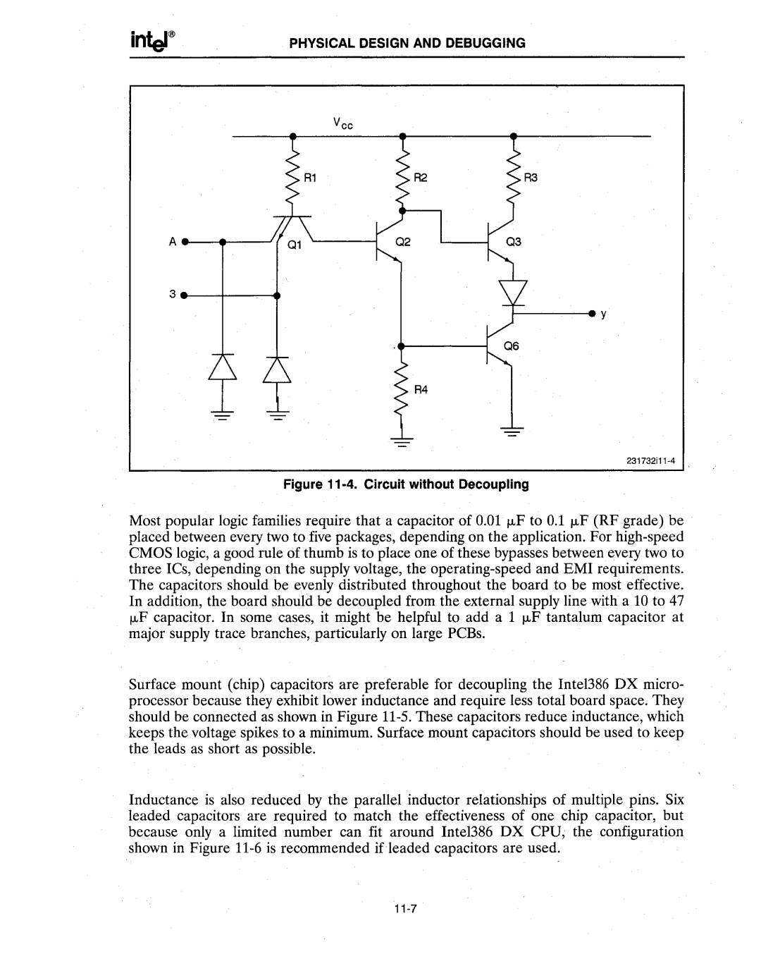
Figure 11-4. Circuit without Decoupling

Most popular logic families require that a capacitor of 0.01 f.LF to 0.1 f.LF (RF grade) be placed between every two to five packages, depending on the application. For high-speed CMOS logic, a good rule of thumb is to place one of these bypasses between every two to three ICs, depending on the supply voltage, the operating-speed and EMI requirements. The capacitors should be evenly distributed throughout the board to be most effective. In addition, the board should be decoupled from the external supply line with a 10 to 47 f.LF capacitor. In some cases, it might be helpful to add a 1 f.LF tantalum capacitor at major supply trace branches, particularly on large PCBs.

Surface mount (chip) capacitors are preferable for decoupling the Inte1386 DX micro- processor because they exhibit lower inductance and require less total board space. They should be connected as shown in Figure 11-5. These capacitors reduce inductance, which keeps the voltage spikes to a minimum. Surface mount capacitors should be used to keep the leads as short as possible.

Inductance is also reduced by the parallel inductor relationships of multiple pins. Six leaded capacitors are required to match the effectiveness of one chip capacitor, but because only a limited number can fit around Intel386 DX CPU; the configuration shown in Figure 11-6 is recommended ifleaded capacitors are used.

11-7

Page 219
Image 219
Intel 386 manual Physical Design and Debugging