PHYSICAL DESIGN AND DEBUGGING
DriverReceiver
Figure 11-16. A.C. Termination
11.4.2.1.6 Active Termination
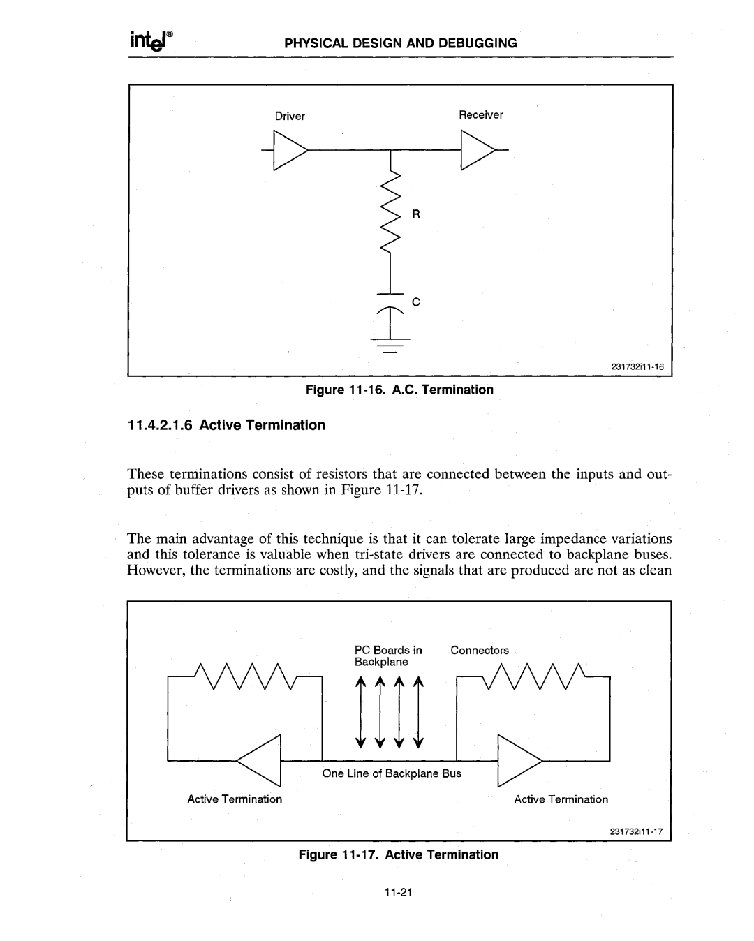
These terminations consist of resistors that are connected between the inputs and out- puts of buffer drivers as shown in Figure
The main advantage of this technique is that it can tolerate large impedance variations and this tolerance is valuable when
PC Boards in Connectors
Backplane
| 1111 |
| One Line of Backplane Bus |
Active Terminati~n | Active Termination |
