LOCAL BUS INTERFACE

UNLOCKED lOCKED lOCKED UNLOCKED

BUS CYCLE BUS CYCLE BUS CYCLE BUS CYCLE

ClK

BE3#-BEO#

A31-A2

lOCK#

NA#

READY#

231732i3-19

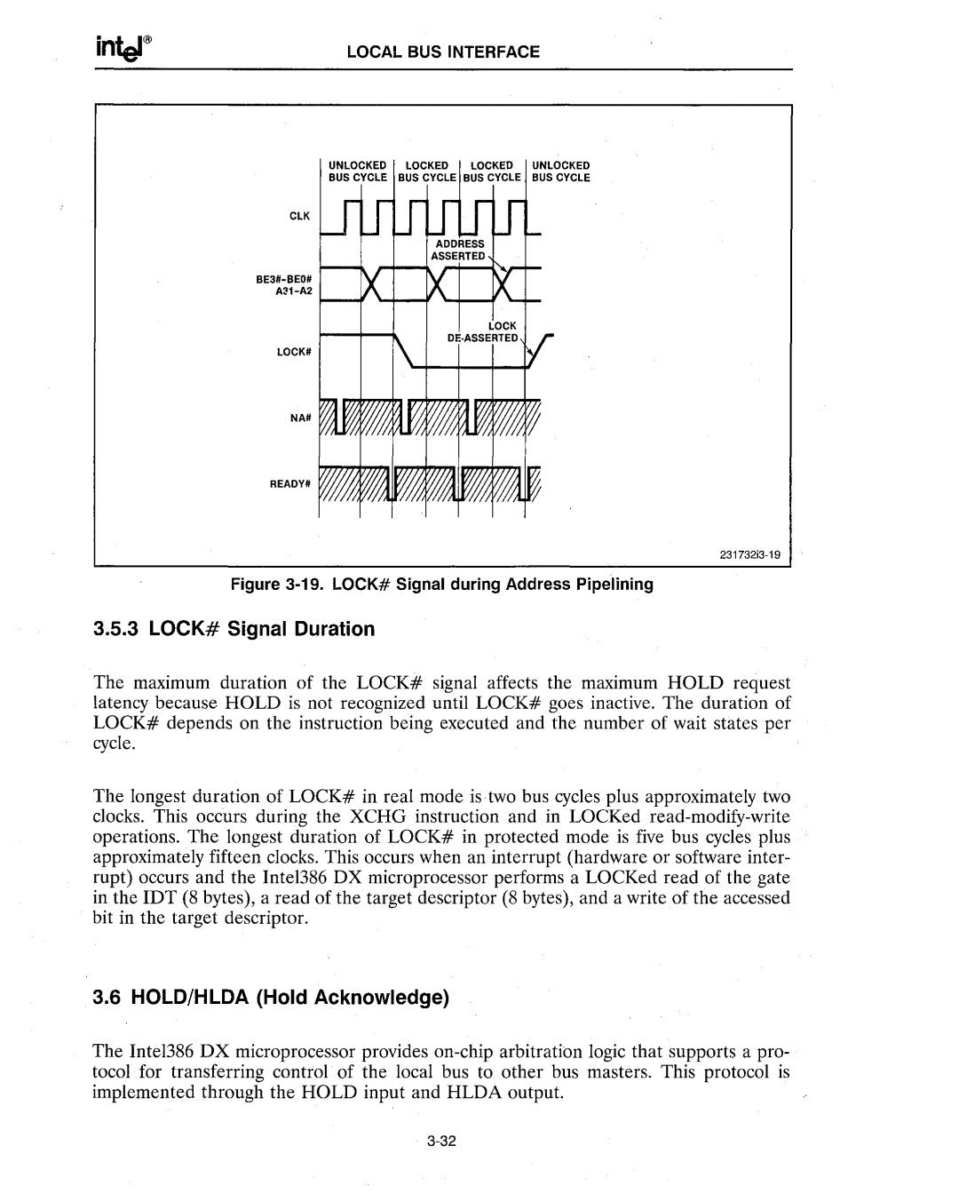
Figure 3-19.LOCK# Signal during Address Pipelining

3.5.3 LOCK# Signal Duration

The maximum duration of the LOCK# signal affects the maximum HOLD request latency because HOLD is not recognized until LOCK# goes inactive. The duration of LOCK# depends on the instruction being executed and the number of wait states per cycle.

The longest duration of LOCK# in real mode is two bus cycles plus approximately two clocks. This occurs during the XCHG instruction and in LOCKed read-modify-write operations. The longest duration of LOCK# in protected mode is five bus cycles plus approximately fifteen clocks. This occurs when an interrupt (hardware or software inter- rupt) occurs and the Intel386 DX microprocessor performs a LOCKed read of the gate in the IDT (8 bytes), a read of the target descriptor (8 bytes), and a write of the accessed bit in the target descriptor.

3.6 HOLD/HLDA (Hold Acknowledge)

The Inte1386 DX microprocessor provides on-chip arbitration logic that supports a pro- tocol for transferring control of the local bus to other bus masters. This protocol is implemented through the HOLD input and HLDA output.
3-32

Page 70
Image 70
Intel 386 manual LOCK# Signal Duration, HOLD/HLDA Hold Acknowledge