PHYSICAL DESIGN AND DEBUGGING
| sx/1 |
| 5V Trace |
|
IV | I | x/1 | S | |
| ?I | ?\ | I | |
| / | I | / | I |
|
| "GND |
| i,U |
| // | /' | GND | |
| ?\" | I | 7'\'< | I |
| I | I | / | I |
|
| |||
|
|
| ||
|
|
| r, =s | |
|
| GND |
| GND |
| / . |
| // |
|
Return or . / ,GNDTrace
| 7'1'< |
| X | I |
|
| I | 7'1 |
| ||
/ |
|
| |||
| I | / , | I | S" | |
|
| I, |
| I, | |
|
|
|
|
| GND | GND |
~ | l./II 5V |
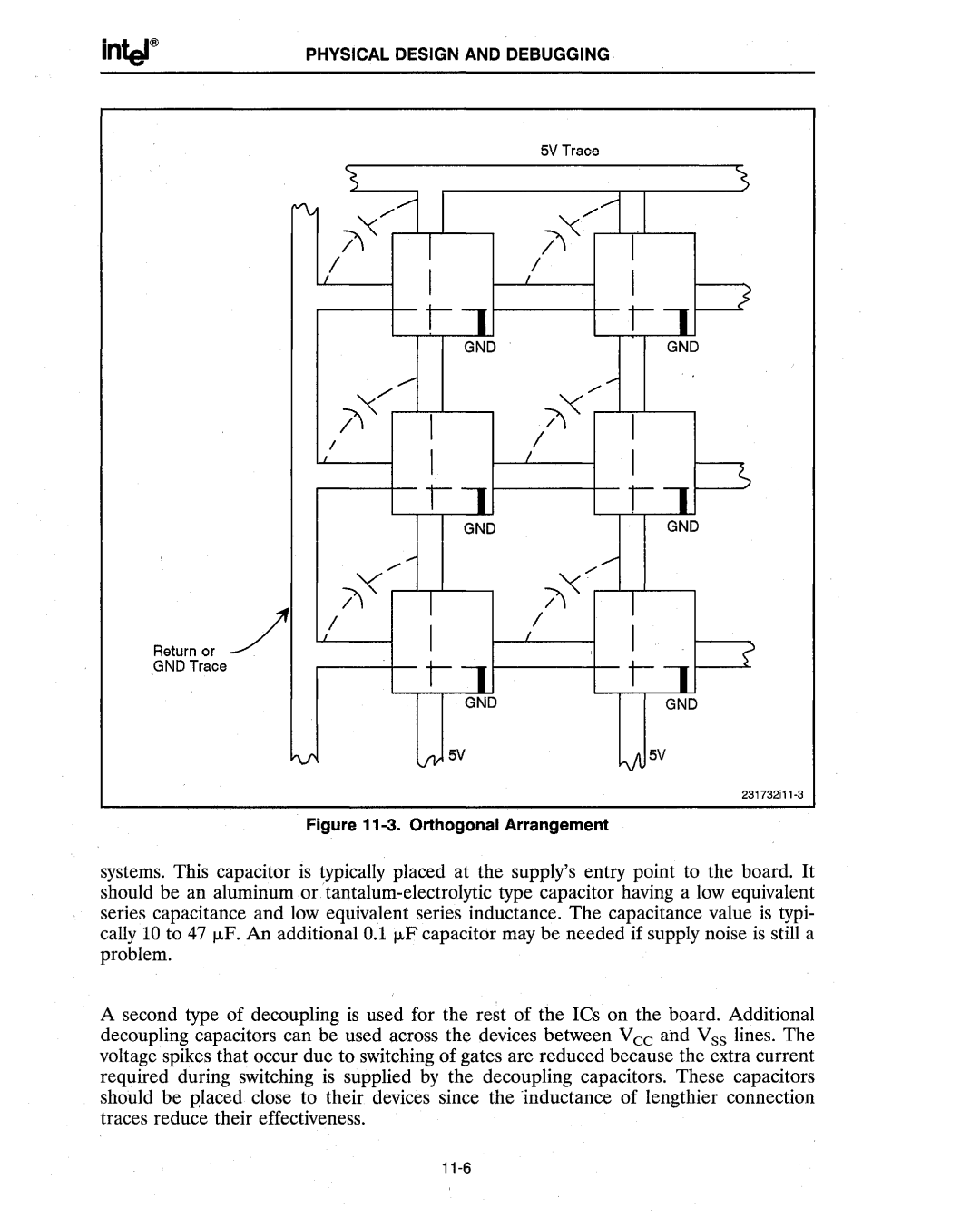
Figure 11-3. Orthogonal Arrangement
systems. This capacitor is typically placed at the supply's entry point to the board. It should be an aluminum
A second type of decoupling is used for the rest of the ICs on the board. Additional decoupling capacitors can be used across the devices between Vee and Vss lines. The voltage spikes that occur due to switching of gates are reduced because the extra current required during switching is supplied by the decoupling capacitors. These capacitors should be placed close to their devices since the