LOCAL BUS INTERFACE
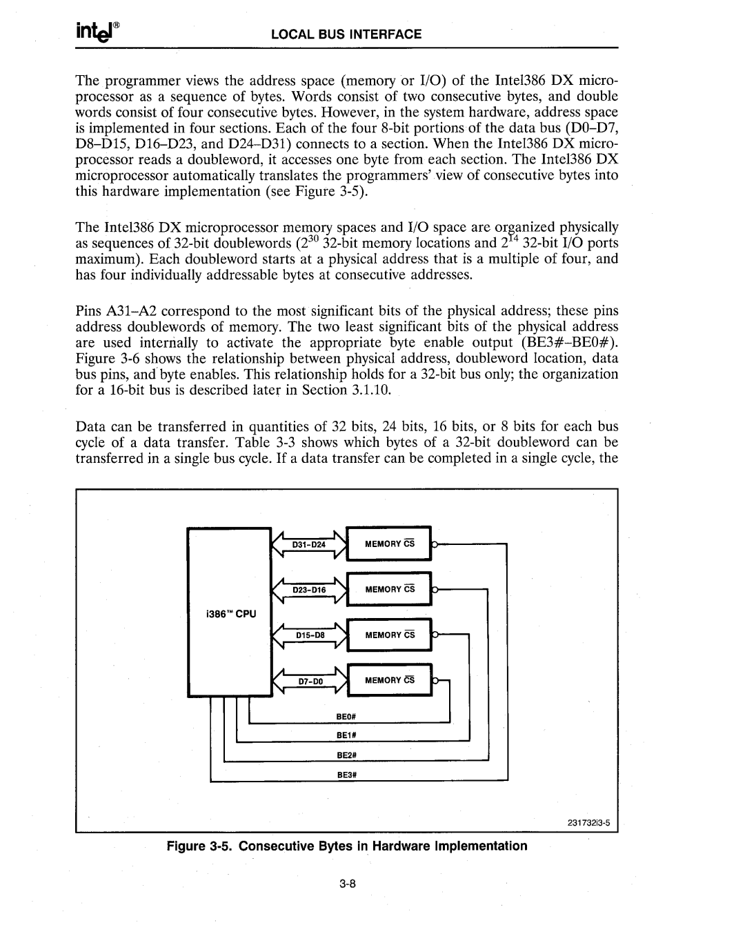
The programmer views the address space (memory or I/O) of the Intel386 DX micro- processor as a sequence of bytes. Words consist of two consecutive bytes, and double words consist of four consecutive bytes. However, in the system hardware, address space is implemented in four sections. Each of the four 8-bit portions of the data bus (DO-D7, D8-DIS, DI6-D23, and D24-D31) connects to a section. When the Intel386 DX micro- processor reads a doubleword, it accesses one byte from each section. The Intel386 DX microprocessor automatically translates the programmers' view of consecutive bytes into this hardware implementation (see Figure 3-S).
The Intel386 DX microprocessor memory spaces and I/O space are or~anized physically as sequences of 32-bit doublewords (230 32-bit memory locations and 2 4 32-bit I/O ports maximum). Each doubleword starts at a physical address that is a multiple of four, and has four individually addressable bytes at consecutive addresses.
Pins A31-A2 correspond to the most significant bits of the physical address; these pins address doublewords of memory. The two least significant bits of the physical address are used interrially to activate the appropriate byte enable output (BE3#-BEO#). Figure 3-6 shows the relationship between physical address, doubleword location, data bus pins, and'byte enables. This relationship holds for a 32-bit bus only; the organization for a 16-bit bus is described later in Section 3.1.10.
Data can be transferred in quantities of 32 bits, 24 bits, 16 bits, or 8 bits for each bus cycle of a data transfer. Table 3-3 shows which bytes of a 32-bit doubleword can be transferred in a single bus cycle. If a data transfer can be completed in a single cycle, the
.A | ..... , | MEMORYCS |
... 031-024 | I/" |
... | ...... | |
023-016 | )I | MEMORYCS |
... | v | |
i386'·CPU | | |
... | ....., I | |
015-08 | ;:t | MEMORYCS |
'I
A.....
... 07-00v MEMORYCS
I BEO#
BE1#
BE2#
BE3#
231732i3-5
Figure 3-5. Consecutive Bytes in Hardware Implementation
3-8