PHYSICAL DESIGN AND DEBUGGING
EPROMs, static RAMs, and peripherals all interface in much the same way. The EPROM interface is the simplest because EPROMs are
The BS16# signal must be activated when the current bus cycle communicates over a
11.8.3 Simplest Diagnostic Program
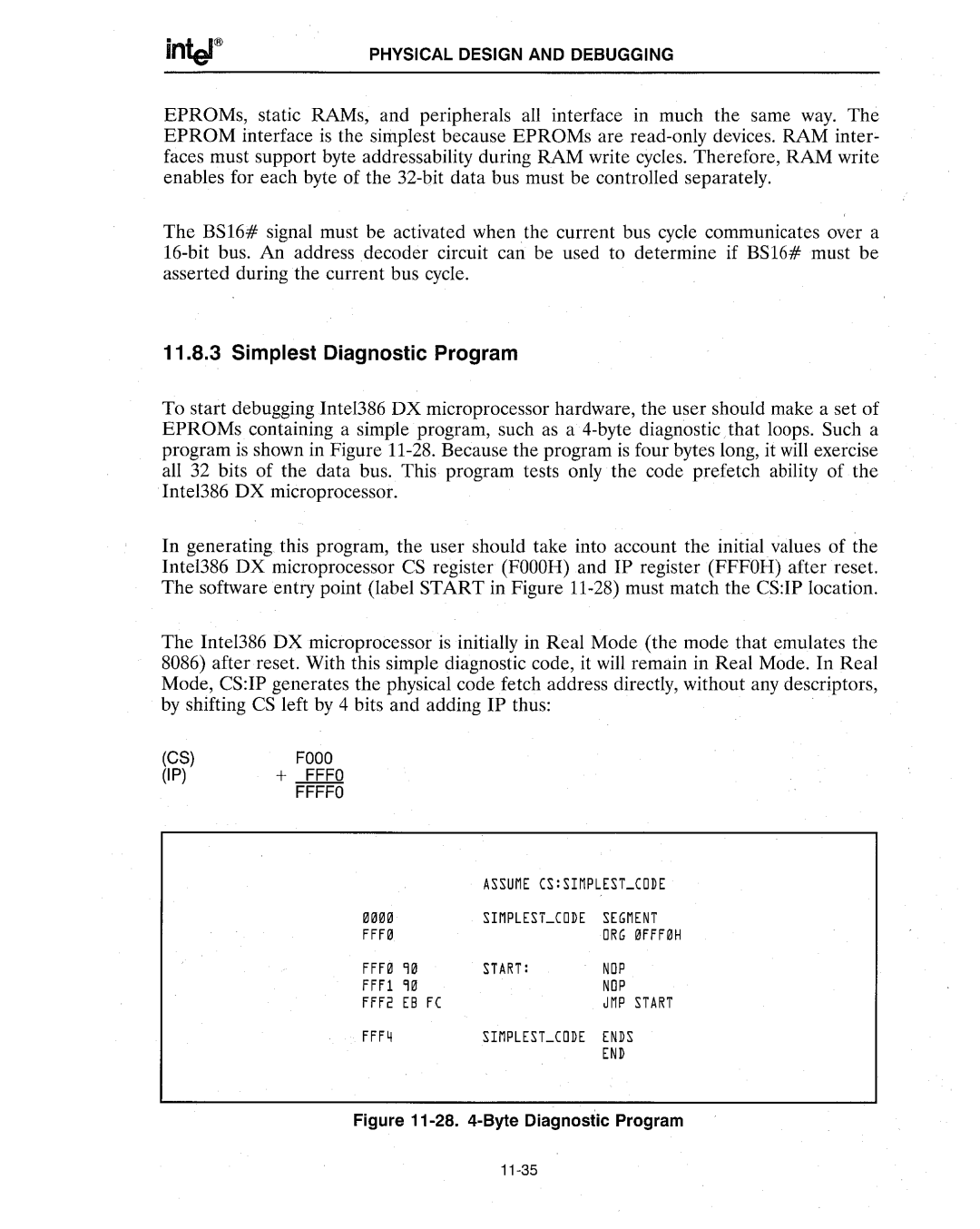
To start debugging Inte1386 DX microprocessor hardware, the user should make a set of EPROMs containing a simple program, such as a
In generating this program, the user should take into account the initial values of the Intel386 DX microprocessor CS register (FOOOR) and IP register (FFFOR) after reset. The software entry point (label START in Figure
The Intel386 DX microprocessor is initially in Real Mode (the mode that emulates the 8086) after reset. With this simple diagnostic code, it will remain in Real Mode. In Real Mode, CS:IP generates the physical code fetch address directly, without any descriptors, by shifting CS left by 4 bits and adding IP thus:
(CS) | FOOO |
(IP) | + FFFO |
| FFFFO |
|
| ASSUME CS:SIMPLEST_CODE | ||
0333 |
| SIMPLESLCODE | SEGMENT | |
FFF3 |
|
| ORG | 3FFF3H |
FFF3 | 93 | START: | NOP |
|
FFFl | 93 |
| NOP |
|
FFF2 | EB FC |
| JMP | START |
FFF4 |
| SIMPLEST_CODE | ENDS |
|
|
|
| END |
|
