lOCAL BUS INTERFACE
CLK2 [
RES# [~'----------5S 5 mml
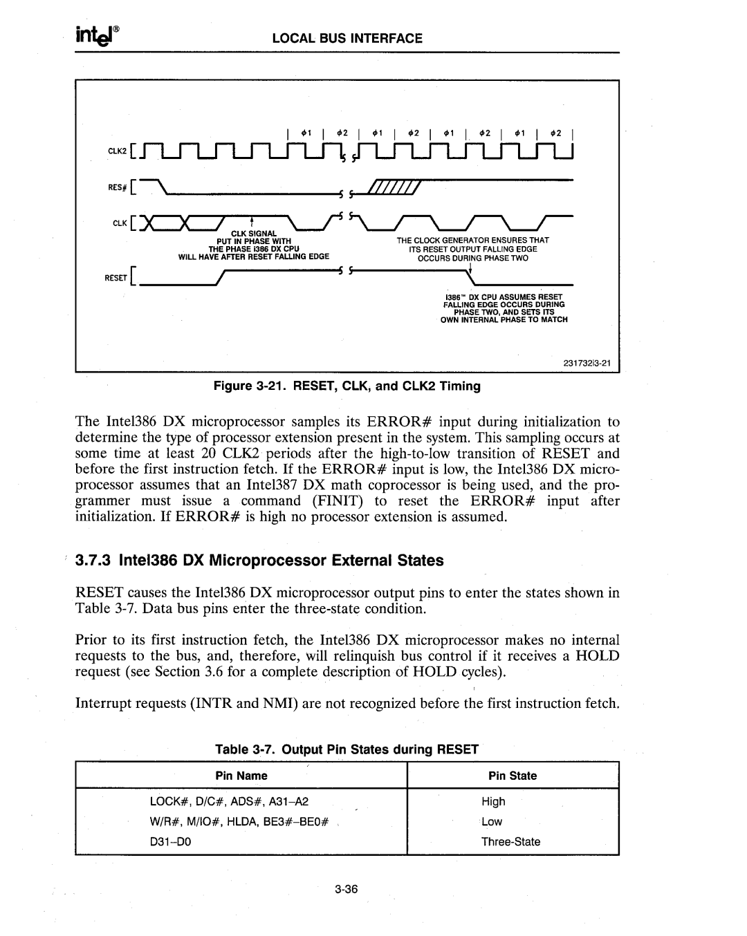
THE CLOCK GENERATOR ENSURES THAT
ITS RESET OUTPUT FALLING EDGE
OCCURS DURING PHASE lWO
RESET [ ____-- 1/, . ------- SS 5-5------.....{'--_____
1386N ox CPU ASSUMES RESET FALLING EDGE OCCURS DURING PHASE lWO, AND SETS ITS
OWN INTERNAL PHASE TO MATCH
Figure 3-21. RESET, ClK; and ClK2 Timing
The Intel386 DX microprocessor samples its ERROR# input during initialization to determine the type of processor extension present in the system. This sampling occurs at some time at least 20 CLK2 periods after the
3.7.3 Intel386 OX Microprocessor External States
RESET causes the Inte1386 DX microprocessor output pins to enter the states shown in Table
Prior to its first instruction fetch, the Inte1386 DX microprocessor makes no internal requests to the bus, and, therefore, will relinquish bus control if it receives a HOLD request (see Section 3.6 for a complete description of HOLD cycles).
Interrupt requests (INTR and NMI) are not recognized before the first instruction fetch.
Table 3-7. Output Pin States during RESET
Pin Name | Pin State |
LOCK#, O/C#, AOS#, | High |
W/R#, M/IO#, HLOA, | Low |
|
