LOCAL BUS INTERFACE
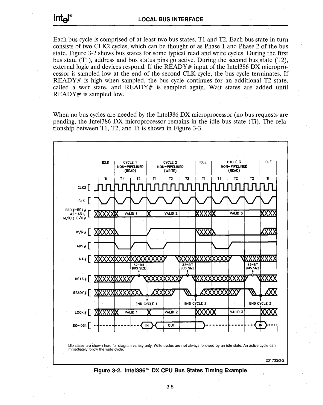
Each bus cycle is comprised of at least two bus states, Tl and T2. Each bus state in turn consists of two CLK2 cycles, which can be thought of as Phase 1 and Phase 2 of the bus state. Figure
When no bus cycles are needed by the Intel386 DX microprocessor (no bus requests are pending, the Intel386 DX microprocessor remains in the idle bus state (Ti). The rela- tionship between Tl, T2, and Ti is shown in Figure
IDLE I | CYCLE 1 | I | CyCLE 2 |
|
|
| CYCLE 3 |
|
| |
|
|
|
|
|
|
| ||||
|
| (READ) |
| (WRITE) |
|
|
| (READ) |
|
|
n | T1 | T2 | T1 | T2 | T2 | TI | T1 | T2 | T2 | n |
CLK2 [ _nIUrL1lrtn-rtn-rtn-rtn-rtn-rtfLrtn-n.rurL1l
CLK [ -VY lrlrlrlrlr\JlrlrV-
W/R# [ | XIXXXXIX |
|
| 1/ |
|
| ,{XXX>" |
| ~ |
ADS # [ | f\.- r - ~I |
| \ - I |
| |||||
NA# [ | IXXXXIXXX | XX | XX |
| ~xxx | XXXIXXX | '<XXXXIXXXX | ||
|
|
|
|
|
| ||||
|
| BusllZE |
|
| BUSiSIZE |
|
| BUStZE | |
8S16 # [ | Xl>\X.X.Xl>\X.X.X y | '(XXXXXXXXY | XXXIXXX | xx | '<M2S.2! | ||||
READY# [ | XIXXXxIXXXX XXX | AM XXJ | ~ | '(XXIXXX | XT | ~ m | |||
|
|
| END CYCLE 1 |
| END CYCLE 2 |
| END CYCLE 3 | ||
LOCK# [ | XIXXXXIX | VALID 1 | IX | VALID 2 | IXXX IX | VALID 3 | IXXXX | ||
00- 031 [ | - |
| |||||||
Idle states are shown here for diagram variety only. Write cycles are not always followed by an idle state. An active cycle can immediately follow the write cycle.
