lOCAL BUS INTERFACE
3.3 CLOCK GENERATION
3.3.1 Clock Timing
The CLK2 and CLK outputs of the clock generator are both
The internal CLK signal of the Intel386 DX microprocessor is matched to the external CLK output by the falling edge of the RESET signal. This operation is described with the RESET function in Section 3.7.
The skew between CLK2 and CLK signals is maintained at 0 nanoseconds (regardless of clock frequency). For closely timed interfaces, peripheral devices must be timed by CLK2. Devices that cannot be operated at the
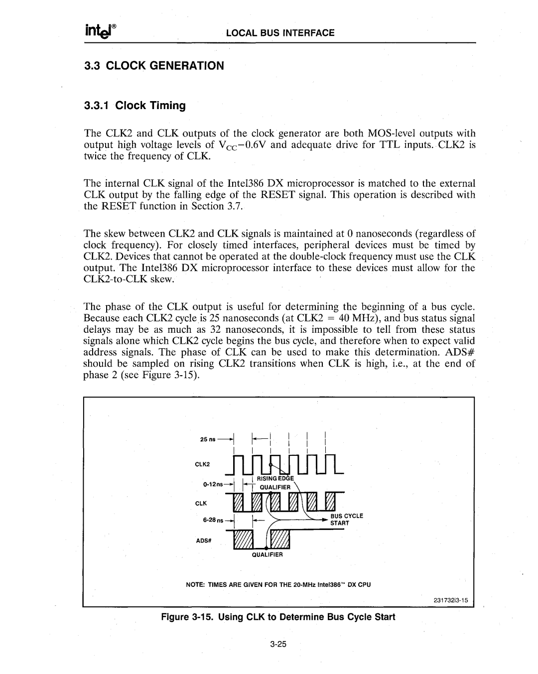
The phase of the CLK output is useful for determining the beginning of a bus cycle. Because each CLK2 cycleis 25 nanoseconds (at CLK2 = 40 MHz), and bus status signal delays may be as much as 32 nanoseconds, it is impossible to tell from these status signals alone which CLK2 cycle begins the bus cycle, and therefore when to expect valid address signals. The phase of CLK can be used to make this determination. ADS# should be sampled on rising CLK2 transitions when CLK is high, i.e., at the end of phase 2 (see Figure
25n.~ ~l I I I
I I II
ClK2 m1...R1I -uuLI
I . I QUALIFIER
ClK
ADS8
NOTE: TIMES ARE GIVEN FOR THE 20·MHzInteI386'"OX CPU