LOCAL BUS INTERFACE
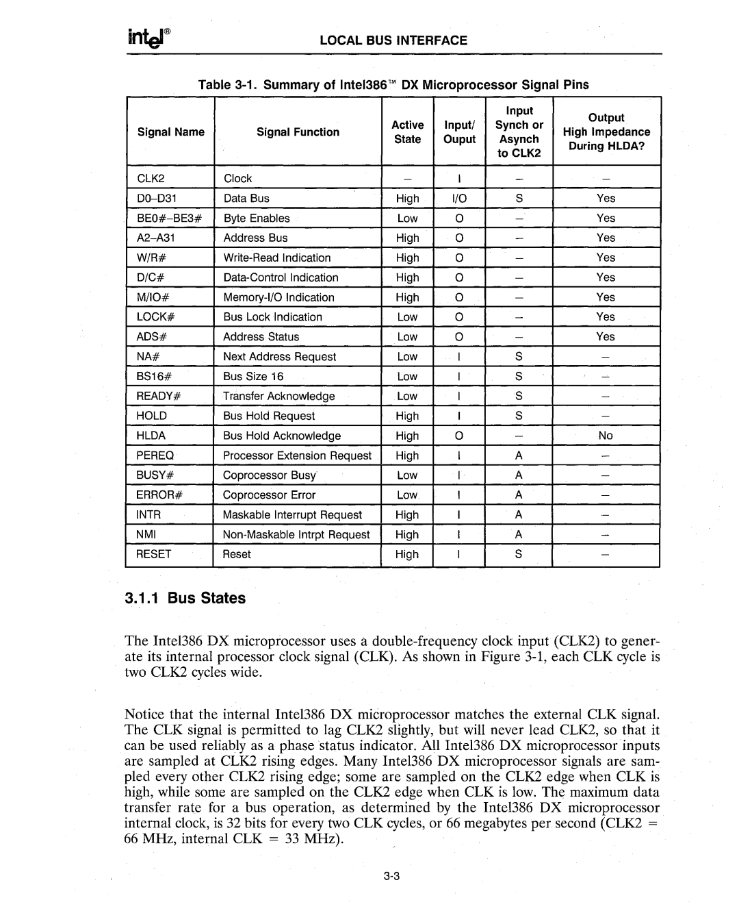
Table 3-1. Summary of Intel386™ OX Microprocessor Signal Pins
|
|
|
| Input | Output | |
|
| Active | Input/ | Synch or | ||
Signal Name | Signal Function | High Impedance | ||||
State | Ouput | Asynch | ||||
|
| During HLDA? | ||||
|
|
|
| to CLK2 | ||
|
|
|
|
| ||
CLK2 | Clock | - | I | - | - | |
Data Bus | High | I/O | S | Yes | ||
Byte Enables | Low | 0 | - | Yes | ||
Address Bus | High | 0 | - | Yes | ||
W/R# | High | 0 | - | Yes | ||
D/C# | High | 0 | - | Yes | ||
M/IO# | High | 0 | - | Yes | ||
LOCK# | Bus Lock Indication | Low | 0 | - | Yes | |
ADS# | Address Status | Low | 0 | - | Yes | |
NA# | Next Address Request | Low | I | S | - | |
BS16# | Bus Size 16 | Low | I | S | - | |
READY# | Transfer Acknowledge | Low | I | S | - | |
HOLD | Bus Hold Request | High | I | S | - | |
HLDA | Bus Hold Acknowledge | High | 0 | - | No | |
PEREQ | Processor Extension Request | High | I | A | - | |
BUSY# | Coprocessor Busy· | Low | I | A | - | |
ERROR# | Coprocessor Error | Low | I | A | - | |
INTR | Maskable Interrupt Request | High | I | A | - | |
NMI | High | I | A | - | ||
RESET | Reset | High | I | S | - |
3.1.1 Bus States
The Intel386 DX microprocessor uses a
Notice that· the internal Inte1386 DX mieroprocessor matches the external CLK signal. The CLK signal is permitted to lag CLK2 slightly, but will never lead CLK2, so that it can be used relia~ly as a phase status indicator. All Inte1386 DX microprocessor inputs are sampled at CLK2 rising edges. Many Inte1386 DX microprocessor signals are sam- pled every other CLK2 rising edge; some are sampled on the CLK2 edge when CLK is high, while some are sampled on the CLK2 edge when CLK is low. The maximum data transfer rate for a bus operation, as determined by the Intel386 DX microprocessor internal clock, is 32 bits for every two CLK cycles,or 66 megabytes per second (CLK2 = 66 MHz, internal CLK = 33 MHz).