LOCAL BUS INTERFACE
HOLD ....SSERTED
READY" ASSERTED-
HOLD NEGATEO-
NO REOUEST
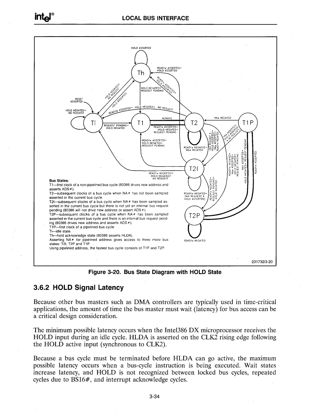
Bus States:
T1-fjrst clock of a non·pipelinedbus cycle (80386 drives new address 811d ' asserts ADS #).
T2-subsequenl clocks of a bus cycle when NA # has not been sampled asserted in the current bus cycle.
T21-subsequent clocks of a bus cycle when NA # has been sampled as- serted in the current bus cycle but there is not yet an internal bus request pending (80386 will not drive new address or assert ADS #).
T2P-subsequent clocks of a bus cycle when NA'has been sampled asserted in the current bus cycle and there is an internal bus request pend- ing (80386 drives new address and asserts ADS').
T1 P-first clock 01 a pipe lined bus cycle. Ti-idle state.
Th-hold acknowledge state (80386 asserts HLDA).
Asserting NA #" for pipelined address gives access to three more bus
states: T21, T2P and T1 P.
Using pipelirfed address, the fastest bus cycle consists of T1 P and T2P.
READY# NEGAT[O
231732i3-20
Figure 3-20. Bus State Diagram with HOLD State
3.6.2 HOLD Signal Latency
Because other bus masters such as DMA controllers are typically used in time-.critical applications, the amount of time the bus master must wait (latency) for bus access can be a critical design consideration.
The minimum possible latency occurs when the Inte1386 DX microprocessor receives the HOLD input during an idle cycle. HLDA is asserted on the CLK2 rising edge following the HOLD active input (synchronous to CLK2).
Because a bus cycle must be terminated before HLDA can go active, the maximum possible latency occurs when a bus-cycle instruction is being executed. Wait states increase latency, and HOLD is not recognized between locked bus cycles, repeated cycles due to BS16#, and interrupt acknowledge cycles.
3-34

