PHYSICAL DESIGN AND DEBUGGING
11.4.1.1 TRANSMISSION LINE TYPES
Although many different types of transmission lines (conductors) exist, those most com- monly used on the printed circuit boards are micro strip lines, strip lines, printed circuit traces,
11.4.1.1.1 Micro Strip Lines
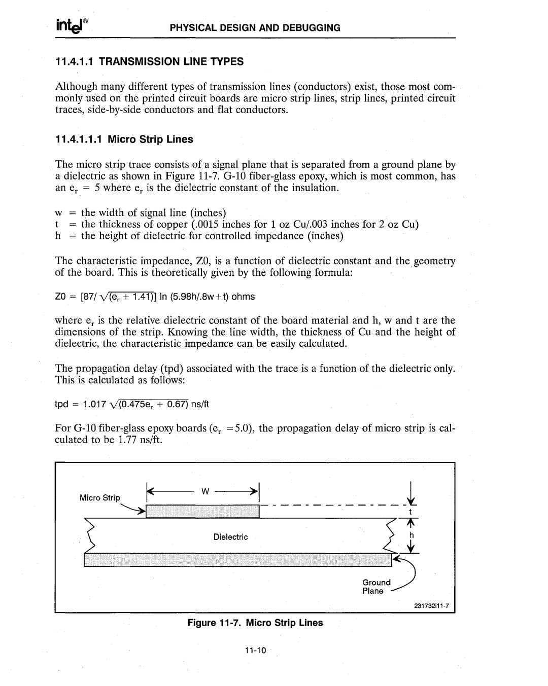
The micro strip trace consists of a signal plane that is separated from a ground plane by a dielectric as shown in Figure
w = the width of signal line (inches) | . |
t= the thickness of copper (.0015 inches for 1 oz CU/.003 inches for 2 oz Cu) h = the height of dielectric for controlled impedance (inches)
The characteristic impedance, ZO, is a function of dielectric constant and the, geometry of the board. This is theoretically given by the following formula:
ZO = [87/v'(er + 1.41)] In (5.98h/.8w+t) ohms
where er is the relative dielectric constant of the board material and h, wand t are the dimensions of the strip. Knowing the line width, the thickness of Cu and the height of dielectric, the characteristic impedance can be easily calculated.
The propagation delay (tpd) associated with the trace is a function of the dielectric only. This is calculated as follows:
tpd = 1.017 v'(0.475er + 0.67) ns/ft
For
Micro Strip
