LOCAL BUS CONTROL PLD DESCRIPTIONS
module iopldl; flag
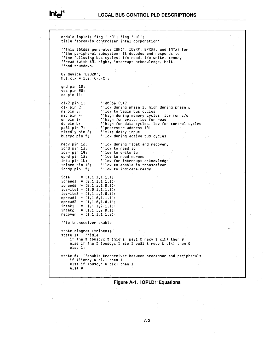
title 'eprom/io controller intel corporation'
"This 85C221l generates IORD#, IOWR#, [PRD#, and INTA# for "the peripheral subsystem. It decodes and responds to "the following bus cycles: i/o read, i/o write, memory "read (with A31 high), interrupt acknowledge, halt, "and shutdown.
U7 device '[1l321l'; h,l,c,x = 1,1l, .C., .X.;
gnd | pin | 11l; |
|
vcc | pin | 21l; |
|
oe | pin | 11; |
|
clk2 pin 1; | "81l386 CLK2 | ||
clk | pin | 2; | "low during phase 1, high during phase 2 |
na | pin | 3; | "low to begin bus cycles |
mio | pin | 4; | "high during memory cycles, low for i/o |
wr | pin | 5; | "high for write, low for read |
dc | pin | 6; | "high for data cycles, low for control cycles |
pa31 | pin | 7; |
| "processor | address A31 | ' |
timedly | pin | 8; | "time delay | input |
| |
buscyc pin | 9; | "low during active bus cycles |
| |||
recv | pin | 12; | "low during float and recovery |
| ||
iord | pin | 13; | "low to read io |
| ||
iowr | pin | 14; | " low to write to |
| ||
eprd | pin | 15; | " low to read eproms |
| ||
inta | pin | 16; | " low for interrupt acknowledge |
| ||
trioen pin | 18; | " low to enable io transceiver |
| |||
iordy | pin 19; | • 'low to indicate ready |
| |||
idle [l,l,l,l,l,lJ ;
ioreadl [1l,l,l,l,l,lJ ;
ioread2 [1l,l,l,l,f/J,lJ ;
iowritel [l,ll,l,l,l,lJ ;
iowrite2 [l,l,l,l,f/J,lJ ;
epreadl [l,l,f/J,l,l,lJ ;
epread2 [l,l,f/J,l,ll,lJ ;
intakl [l,l,l,ll,l,lJ ;
intak2 [l,l,l,f/J,Il,lJ ;
recover 11,1,1,1,1,f/Jl;
"io transceiver enable
state_diagram [trioenl;
state 1: "idle
if (na & !buscyc & !mio & !pa31 & recv & clk) then Il else if (na & !buscyc & mio & pa31 & recv & clk) then f/J else 1;
state fIJ: "enable transceiver between processor and peripherals if (!iordy & clk) then 1
else if (buscyc & clk) then 1 else iii;