IBM
Page
IBM
Ninth Edition November
Research Triangle Park NC USA
Contents
Conguration Process Config Talk 6 and Commands
Part 2. Understanding, Conguring, and Using Base Services
Conguring and Monitoring the Config Process
Boot Config Process
Protocol Qcong Set Time Unpatch Update
Conguring Boot Config
Messaging Monitr Talk 2 Process
Using the Event Logging System ELS
Operating/Monitoring Process Gwcon Talk 5
145
Conguring and Monitoring the Event Logging System ELS
Getting Started with Network Interfaces
Part 3. Understanding, Conguring and Operating Interfaces
Conguring and Monitoring Performance
Conguring Ieee 802.5 Token-Ring Network Interfaces
Overview of LAN Emulation
Using the Ethernet Network Interface
Conguring and Monitoring the Ethernet Network Interface
Conguring and Monitoring ATM
Conguring and Monitoring LAN Emulation Clients
Using LAN Emulation Clients
Using the X.25 Network Interface
Conguring Serial Line Interfaces
327
XTP Conguring Commands 375 Add Change 378
Conguring and Monitoring the X.25 Network Interface
Conguring and Monitoring XTP
Conguring and Monitoring Frame Relay Interfaces
Using Frame Relay Interfaces
387
405
Using Point-to-Point Protocol Interfaces
Conguring and Monitoring Point-to-Point Protocol Interfaces
Conguring and Monitoring Multilink PPP Protocol MP
Using the Multilink PPP Protocol
Using Sdlc Interfaces
Conguring Sdlc Relay
Conguring and Monitoring BSC Relay
Using Binary Synchronous Relay Brly
Using the V.25bis Network Interface
Conguring and Monitoring the V.25bis Network Interface
Using the Isdn Interface
Using the V.34 Network Interface
Conguring and Monitoring the V.34 Network Interface
Conguring and Monitoring Dial Circuits
Conguring and Monitoring the Isdn Interface
Appendix A. Quick Conguration Reference
Appendix C. Making a Router Load File from Multiple Disks
Appendix B. X.25 National Personalities
Readers Comments Ð Wed Like to Hear from You
Figures
Xix
Xx MRS V3.2 Software Users Guide
Tables
Xxi
Xxii MRS V3.2 Software Users Guide
Xxiii
Xxiv MRS V3.2 Software Users Guide
All other copies of the documentation
Resulting from this authorization
For online versions of this book, you are authorized to
Exclusion may not apply to you
Xxvi MRS V3.2 Software Users Guide
Trademarks
Xxviii MRS V3.2 Software Users Guide
About the Software
Preface
Who Should Read This Manual
Xxix
Separately from the device as part of the software order
Conventions Used in This Manual
IBM 2210 Nways Multiprotocol Router Publications
Ctrl-P
SC30-3992
Safety SD21-0030
Operations and Network Management SC30-3681
SC30-3680
Planning and Installation GA27-4068
GC30-3867
Summary of Changes
Editorial Changes
Moved into the Using and Conguring Featuresbook
Clarications and corrections
Part 1. Understanding and Using the Software
MRS V3.2 Software Users Guide
Before You Begin
Accessing the Software Using Local and Remote Consoles
Getting Started
Migrating to the Current Release
Local Consoles
Logging In Remotely or Locally
Remote Login Names and Passwords
Remote Consoles
Telnet Connections
Reloading or Restarting the Router
Exiting the Router
Discussing the User Interface System
Understanding the First-Level User Interface
Same as the Opcon process
Quick Conguration Process
System Security
Automatically starts Cong-Only and then enters Quick Cong
Connecting to a Process
Using the Software
Entering Commands
Status
Identifying Prompts
Getting Help
Some Conguration Suggestions
Exiting a Lower Level Environment
Getting Back to Opcon
Creating a First Conguration
Basing a Conguration on an Existing Conguration
Basing on an Existing Conguration
Permanently Updating a Conguration
Accessing the Second-Level Processes
Temporarily Updating a Conguration
Restarting or Reloading the Router
Accessing the Conguration Process, Config Talk
Entering the Config Process
Are you sure you want to restart the router? Yes or No yes
Entering the Gwcon Command Process
Accessing the Operating/Monitoring Process, Gwcon Talk
Accessing the Third-Level Processes
Accessing the Network Interface Conguration Process
Following example adds a dial-in circuit
Config list devices
Following example adds a dial circuit interface
Following example adds a dial-out circuit
Architecture
Accessing the Network Interface Console Process
Network Architecture Supported Interfaces
Accessing the Feature Processes
Accessing Feature Conguration and Operating Processes
Accessing Protocol Conguration and Operating Processes
Entering a Protocol Conguration Process
Entering a Protocol Operating Process
Config protocol IP
+configuration
+ protocol
Enter
Command History for Gwcon and Config Command Line
Repeating a Command in the Command History
Ctrl-Bfor Backward, and the current line is replaced with
Starting a Repeat Sequence As Commands Are Entered
Repeating a Series of Commands in the Command History
Example
Starting a Repeat Sequence After All Commands Are Entered
Enter the following commands in Gwcon
MRS V3.2 Software Users Guide
Opcon Process
MRS V3.2 Software Users Guide
Accessing the Opcon Process
Using Opcon
Opcon Commands
Syntax Breakpoint
Breakpoint
Divert
Syntax Divert
Flush
Halt
Logout
Intercept
Memory
Syntax pause Example
Pause EasyStart only
Memory Example
Memory
Restart
Reload
Status
Two dashes
Stop EasyStart only
TTY1 or TTY2
Comments
Syntax Talk
Talk
Telnet
Example talk
Ip-address terminal-type
Three clients outbound from the router
Syntax Telnet
Display
Not connected to a host
Send ayt
Part 2. Understanding, Conguring, and Using Base Services
MRS V3.2 Software Users Guide
Conguration Process Config Talk 6 and Commands
What is CONFIG?
Configclear all
Using EasyStart
Using the Config Talk 6 Process
Configclear device
Automatic Entry Into Cong-Only Mode
Cong-Only Mode
Manual Entry Into Cong-Only Mode
Boot to Cong-Only mode
Quick Conguration
Manual Entry Into Quick Cong Mode
Automatic Entry Into Quick Cong Mode
Exiting from Quick Cong Mode
Technical Support Access
Conguring User Access
Conguring Spare Interfaces
Access the Gwcon process by entering talk
Add a dial circuit using the add device command
Commands
Restrictions for Spare Interfaces
IPv6
Activate them on the network using the activate command
OSI/DECnet
Resetting Interfaces
Configprotocol ipx
Restrictions for Resetting Interfaces
Talk 6 Confignet 1 PPP Config
Talk 5 +reset
DNA
Using the Config Talk 6 Process
Config Commands
Conguring and Monitoring the Config Process
Entering and Exiting Config
Enter the Opcon talk command and the PID for Config
Config Commands
Network-subdial-address
Address-name
Network-dial-address
Ppp-user
Default value no
Password
Allow inbound access
Default value
Hostname
Default value none
Net-Route Mask
Time-Allotted
Disable user
Conguring Features
Example with ECP encryption
Shared Secret
Tunnel tunnel-name
Set shared secret
Tunnel-Server endpoint address
Do you want to add Technical Support access?
Enter password
Enter password again
Enter permission
Change
Boot
Syntax Boot
Device dial-circuit
Enter new password again
Enter current password
Enter new password
Syntax Change pppuser Encryption-key Parameters Password
Tunnel-prole
Clear
Syntax Clear
Default value is ªdisabledº
Wrs WAN Restoral feature
Command
Ip IP
Syntax Delete
Delete
Example clear els
Isdn-address address-name
Disable
Enable
Enable Console-login Interface Modem-control
Modem-control carrier-wait or ring-wait service1 or service2
Environment
Environment Commands
Environment Command Summary
Syntax Environment
Event
Feature# or feature-short-name
Feature
Syntax Feature
List
Conguration
Tunnel-prole Users V25-bis-address V34-address
Devices device or devicerange
Displays conguration information about the router
Patches
Isdn-address
Displays the current Isdn address congurations
Pppusers
Encr encryption
Call callback
Dial dialback
Tunnel Name
Networkinterface#
Network
Patch
Syntax Patch
Bgp-subnets new value
Ip-default-ttl #ofpackets
Valid Values 0 to Default Value Ospf-import-rate rate
Dls-ignore-lfs new value
Performance
Protocol
Syntax Qcong
Qcong
Set
Baud-rate
# of seconds
Conguration command
Interface#
Global-buffers max#
Inactivity-timer #ofmin
Logging disposition setting
Additional functions as described in Table
Only to increase it
Prompt-leveluser-dened-name
Set prompt
Spare-interfaces n
Time
Receive-buffers interface# max#
Syntax Time
Unpatch
Update
Valid values -720 to Default value
Offset minutes
Config Commands
Config Commands
What is Boot CONFIG?
Boot Config Process
Conguring Booting
Device as a Bootp Client
Using a Device as a Boot Server
How the Bootp Forwarding Process Works
Using the Boot Config Process
Conguring a Bootp Server
Device as a Bootp Relay Agent
Enabling/Disabling Bootp Forwarding
IP Config enable bootp IP Config disable bootp
Using the Trivial File Transfer Protocol Tftp
IP Config add BOOTP-SERVER IP address of server
Filename Denitions for IBD
Accessing Conguration Files From a Remote Host or Router
Example 1 test.cfg
Conventions for File Name Extensions
IBD Considerations When Transferring a File
Validating the Conguration Load
Type of File Filename Extension
Conguring Dumping
Tftp Server, Boot and Dump Directories
Loading an Image at a Specic Time
Dump Files
Status
Installing Software/Code
Talk
Boot config list boot-entries
Enter exit
Using the Boot Config Process
Boot Config Commands
Conguring Boot Config
Entering and Exiting Boot Config
Boot Config Commands
Syntax Add
Boot-entry
Add
Address
Bp-device
Add Boot Entry Parameters
Loads/name
Add dump-entry
Changeaddress Boot-entry Bp-device Dump-entry
Dump-entry
File name ? c\dump\gertrude.dmp
Change bp-device Change which entry 1?
Change address
Change dump-entry
Copy
Ibd or lename
Removes the specied interface as a Bootp device
Address #
Describeloadname
Disabledumping Unique-naming
Describe
Loadname
Syntax Erase
Erase
Unique-naming
Loadname or bank-number
Addresses
Dump-entries
Boot-entries
Displays the boot le conguration
List bp-device
Local loadname
Load
Syntax Load Local Remote
List view
Store
Timedload
Example 1. Load image source is a remote host
Deactivate
Example 1. Deactivate time activated load
Example 2. Load image source is the IBD
Remote Host
Syntax Tftp Get Put
Local lename
Host lename
Remote Host?
Console display is the same as the Tftp get command
Local lename?
Host lename?
MRS V3.2 Software Users Guide
Boot Method Description
Boot Options
Description of Boot Methods
111
Unsuccessful Bootp
Bootp Using a Console Terminal
* indicates that the load image has nished loading
Boot Options Available
Booting from a Tftp host server using a console terminal
Accessing the Boot Options
Boot Options
Boot Option Prompts
Option Name Description
Ethernet Prompts
Boot Option Prompts
Prompt Description
Token Ring Prompts
If you enter IBD, you see the following
BC Boot in Cong-only Mode
To reload the current conguration, pressEnter
BM Boot using console queries
If you enter Ethernet, you see the following
If you enter Ethernet, you see the following
BN Boot, But Do Not Run, Using Console Queries
BP Boot using Bootp
Dump using stored conguration
Diag Execute IBM Extended Diagnostic Program
DM Dump using Console Queries
UB Display Tftp Boot Conguration
UC Display Hardware Conguration
This option is used only by your service representative
UG Go execute at address in RAM
If you enter Token Ring, you will see the following
LC Load Conguration Memory
If you enter WAN, you see the following
ZC ZModem conguration memory load
ZB ZModem Boot
CC Clear Conguration Memory
Enter y and the console displays the message
Conguring
MRS V3.2 Software Users Guide
Gwcon Commands
Operating/Monitoring Process Gwcon Talk 5 and Commands
What is GWCON?
Entering and Exiting Gwcon
Activate
Syntax boot Example
Gwcon Command Summary
Gwcon Process
Network# or rangeofnetwork#
Buffer
Syntax Buffer
Interface
Interface# or rangeofinterface#
Conguration
Bytes Alloc
Syntax Conguration
Type of MAC/Data link congured for the interface
Configuration
MAC/Data Link
Hardware
State Current state of the network interface
Testing
Disabled
Available
Not Present
Disableinterface#
HW Mismatch
Input Errors
Error
Syntax Error
Input Discards
Fault
Interface
Log
Syntax memory Example
Physical installed memory
Syntax Log
Total routing memory
Perm Alloc
Reserve
Never Alloc
Temp Alloc
Bisync BSC
X.25 interface by entering the X.25 operating commands
For the following network and link-layer interfaces
Ethernet
Queue
Queue
Reset
Statistics
Bytes Trans
Test
Uptime
Number of bytes transmitted at the MAC layer
Syntax Uptime
Gwcon Process
Messaging Monitr Talk 2 Process
What is Messaging MONITR?
Commands Affecting Messaging
Entering and Exiting the Messaging Monitr Process
Messaging Monitr
ELS is a subprocess that you access from the Opcon process
Using the Event Logging System ELS
What is ELS?
147
Event Logging Concepts
Using ELS
Entering and Exiting the ELS Conguration Environment
Causes of Events
Event Number
Interpreting a Message
Subsystem
Logging Level
Logging Levels
Packet Completion Codes Error Codes
Message Text
Logging Level Type
Groups
Using ELS
To delete a group, use the delete command
ELS displays network information as follows
Managing ELS Message Rotation
See ªUsing ELS Message Bufferingº on
Following message is displayed
ELS Example
Using ELS to Troubleshoot a Problem
Conguring ELS So Event Messages Are Sent In Snmp Traps
Display subsystem srt all Display subsystem br all
Talk
Syslog Facility and Level
Using and Conguring ELS Remote Logging
Remote Workstation Conguration
Using ELS
Conguring the 2210 for Remote Logging
Syslog.conf Conguration File
ELS configset remote local-id ** IBM/2210
ELS configset remote source-ip-addr
ELS configset remote remote-ip-addr
ELS configset remote no-msgs-in-buffer
Remote Logging Output
Conguring Subsystems and Events for Remote Logging
Sample Contents from Syslog News Info File
Msg
Output from Talk
Additional Considerations
ELS Messages Containing IP Addresses
Duplicate Logging
Using ELS Message Buffering
Recurring Sequence Numbers in Syslog Output Files
None
Using ELS
MRS V3.2 Software Users Guide
ELS Conguration Command Summary
Accessing the ELS Conguration Environment
ELS Conguration Commands
Conguring and Monitoring the Event Logging System ELS
Conrm the creation of a new group
ELS Conguration Commands Talk
Groupname subsystem.eventnumber
This environment you congure message buffering
Default
Display
Lter-status
Filter
Syntax Filter Net
Groups
Lists all events in a specied subsystem
Subsystem
Subsystem subsystem
Subsystems all
Trace-status
Nodisplay
Noremote
Nodisplayevent Group Range Subsystem
Subsystem subsystem.name syslogfacility sysloglevel
Noremoteevent Group Range Subsystem
Group group.name
Suppresses the remote logging of all ªtkrº messages
Notraceevent Group Range Subsystem
Notrace
Notrap
Syntax Notrap
Remoteevent Range Group Subsystem
Remote
Notrap range gw 19
Remote subsystem TKR all loguser loginfo
Remote range gw 19 22 loguser loginfo
Group group.name syslogfacility sysloglevel
Syntax Set remote-logging
Pin maxtraps
Remote-logging
Facility
Sourceipaddr
No-msgs
Remoteipaddr
Localid
Timeofday
Default-bytes-per-pkt bytes
Timestamp timeofday or uptime or off
Syntax Set trace
Wrap-mode off or on
Trace
Stop-event event id
Syntax Trace
Syntax Trap
ELS Net Filter Conguration Commands
Trap
Trap range gw 19
Create
Syntax Create queue
Enable
Disable
Delete
Log
ELS Message Buffering Conguration Commands
List
All
Nolog
Syntax Nolog
Set
Stop string text or none
Default value off
Entering and Exiting the ELS Operating Environment
Wrap on or off
Advanced
ELS Monitoring Commands
ELS Monitoring Commands Talk
Environment you change message buffering operation
Subsystem subsystem.name
Files
Event subsystem. event#
Displays messages for the specied event subsystem.event#
Lename
Syntax Les trace tftp
HostIPaddr
Syntax Lter Net
List pin
Groups group.name
List event ip.007
List subsystem eth
Run-time information
Subsystem all
Occurred on the router
Suppresses the displaying of messages for the specied event
Level, such as there is with Remote
Gw.21, and gw.22
Syntax Notrace
Suppresses the display of the specied tracing event
Subsystem subsystemname logging-level
Syntax Packet-trace
Notrap subsystem tkr error
Packet Trace
Remoteevent Group Range Subsystem
Syslogfacility
Remote event gw.019 loguser loginfo
Sysloglevel
Remove
Restore
Syntax Restore
Retrieve
Syntax Retrieve
Save
Syntax Save
Facility
Timestamp
Syntax Set timestamp Timeofday or uptime or off
Syntax statistics
Decode off or on
Wrap-mode off/on
Example statistics
Not
Name of subsystem
Subsys
Vector
View
Syntax View
Current
Off
Syntax Off
Subsystems
Reset
Syntax Subsystems
View
ELS Net Filter Monitoring Commands
Trace-Status
Syntax Trace-status Example
ELS Net Filter Monitoring Commands
Syntax Create queue
All Lists all currently congured lters
All Enable all currently congured lters
Lists the lter specied bylter#
Flush
ELS Message Buffering Monitoring Commands
ELS Message Buffering Monitoring Commands
Release the buffer memory for other use by the system
Nolog
Buffer-size Mbytes
Buffer-size Mbytes
Buffer formatted destipaddress destlename
Command to a remote host
New messages at the beginning of the buffer on
System prompts you for it
Noscroll
Scroll
Number
Performance Overview
Accessing the Performance Conguration Environment
Conguring and Monitoring Performance
Performance Reporting Accuracy
Talk 6 Config
Performance Conguration Commands
Perf Conguration Command Summary
T2 output
Performance Conguration Commands Talk
Accessing the Performance Monitoring Environment
Performance Monitoring Commands
Settime
Report
Performance Monitoring Commands Talk
Syntax report Example
Time
Performance Monitoring Commands Talk
Part 3. Understanding, Conguring and Operating Interfaces
221
MRS V3.2 Software Users Guide
Before You Continue
Network Interfaces and the Gwcon Interface Command
Getting Started with Network Interfaces
223
Dening Spare Interfaces
Getting Started with Network Interfaces
Token-Ring Conguration Command Summary
Accessing the Token-Ring Interface Conguration Process
Token-Ring Conguration Commands
Conguring Ieee 802.5 Token-Ring Network Interfaces
Packet-Size
Conguring Token-Ring Network Interfaces
Source-routing
Syntax Set Physical-address Rif-timer
Set rif-timer
Token-Ring 4/16 Valid Packet Sizes
Accessing the Interface Monitoring Process
Speed
Dump
Token-Ring Interface Monitoring Commands
Token-Ring Monitoring Command Summary
Syntax dump Example
Self-Test Pass
Token-Ring Interfaces and the Gwcon Interface Command
Statistics Displayed for 802.5 Token-Ring Interfaces
Self-Test Fail
Using the Gwcon Interface Command
Auto-removal errors
# of times signal lost
Hard errors
Ring recovery actions
Token errors
Lobe wire faults
Burst errors
Removes received
Using the Gwcon Interface Command
LLC Conguration Command Summary
Accessing the Interface Conguration Process
LLC Conguration Commands
Conguring and Monitoring LLC Interfaces
Conguring LLC
N3-framesrcvd-before-ack
T1-reply-timer
N2-max-retry
Rw-receive-window
Ti-inactivity-timer
T2-receive-ack-timer
Tw-transmit-window
Monitoring LLC
LLC Monitoring Commands
Clear-Counters
Syntax Clear-counters
Rcvd I-frame before ACK N3
SAP value in hex 0FE
MAX I-eld Size N1
Transmit Window Size Tw
Cumulative number of sessions
Disconnecting
Frames refused by LLC user
Number of active sessions
FRMRReceived
Resetting
RemoteBusy
Session
Remote MAC addr
Access Priority
Session Id
Source MAC addr
Last ACKd sent frame Va
Current send seq Vs
Current Rcv seq Vr
No. of frames in ACK pend q
N2-maxretry
N3-frames-rcvd-before-ack
Monitoring LLC
Number of self-tests that succeeded
Using the Ethernet Network Interface
247
Number of self-tests that failed
Using Ethernet Network Interfaces
Internal mac tx errors or internal MAC trans errors
Failed, carrier check or failed, carrier sense error
CD heartbeat error or SQE test error
Multiple collisions
Using Ethernet Network Interfaces
Ethernet conguration prompt ETH Config, is displayed
Accessing the Ethernet Interface Conguration Process
Ethernet Conguration Commands
Conguring and Monitoring the Ethernet Network Interface
IP-Encapsulation
Connector-Type
Ethernet Conguration Commands Talk
Physical-Address
Ethernet monitoring command Summary
Accessing the Ethernet Interface Operating Process
Ethernet Interface Monitoring Commands
Collisions
Ethernet Interface Monitoring Commands Talk
Syntax collisions Example
LAN Emulation Benets
Overview of LAN Emulation
255
Overview of LAN Emulation
Simple LAN Emulation Network
LAN Emulation Components
Physical Network Logical Network
Broadcast and Unknown Server BUS
Addressing in ATM
ATM uses 20-byte hierarchical addressing
ESI
ATM Addresses of LAN Emulation Components
Locating the Lecs Using Ilmi
Manual Conguration of the Signaling Version
Overview of Related Ilmi Functions
Overview of the Lecs Function
Overview of LAN Emulation
LAN Destination Policy
Sample Situations for Use of the Lecs Assignment Policies
ATM Address Policy
Elan Name Policy
Max Frame Size Policy
More Information About TLVs
Elan Type Policy
Duplicate Policy Values
From LE client to LES
Connecting to the LES
Control Direct VCC bidirectional point-to-point
Control Distribute VCC point-to-multipoint
Connecting to the BUS
Address Resolution
Address Registration
From LE client to BUS
BUS Functions
Multicast Send VCC bidirectional point-to-point
Multicast Forward VCC point-to-multipoint
Overview of Extensions for LAN Emulation
Establishing Data Direct VCCs
Broadcast Manager
BCM Support for IP
BCM Support for IPX
BCM Support for NetBIOS
BCM Support for Source Route Bridging
LAN Emulation Reliability
LAN Emulation Redundancy
LAN Emulation Security
Key Conguration Parameters for LAN Emulation
LEC
ATM and LAN Emulation
Using ATM
How to Enter Addresses
273
ATM Virtual Interface Concepts
Advantages of Using ATM Virtual Interfaces
ATM-LLC Multiplexing
Conguring ATM and LAN Emulation
Disadvantages of using ATM Virtual Interfaces
ATM Virtual Interface Conguration Concepts
ATM Virtual Interface Conguration Concepts
Conguring and Monitoring ATM
Accessing the ATM Interface Conguration Process
277
ATM Conguration Commands Talk
ATM Conguration Commands
ATM Interface Conguration Commands
ATM Conguration Command Summary
Example list con
Esi esi-address
Syntax List Conguration Esi
Example list esi
Syntax Qos-conguration
ATM Interface Conguration Commands Talk
QoS Conguration
Max-data-rate speed
Max-calls
Default Value Example
Valid Values
Max-callers
Max-frame
Max-mp-parties
65535
On or OFF
You are prompted for the VPI/VCI range you want to trace
Uni-version
Network-id
Valid Values Default Value
UNI
Address of End System Identiers
ATM Virtual Interface Conguration Command Summary
Accessing the Virtual ATM Interface Conguration Process
ATM Virtual Interface Conguration Commands
Syntax add Example
ATM Virtual Interface Conguration Commands Talk
Accessing the ATM Monitoring Process
ATM Monitoring Commands
Syntax Remove Example remove
ATM Monitoring Commands Talk
ATM Interface Monitoring Commands ATM INTERFACE+ Prompt
Syntax Atm-llc
Lists the reserved bandwidth on the ATM Interface
ATM Interface Monitoring Commands Talk
Reserved-bandwidth
List
Syntax Wrap
Wrap
Off Stops packet tracing on all VCCs
Start
ATM LLC Conguration Command Summary
ATM-LLC Monitoring Commands
ATM Virtual Interface Monitoring Commands
Syntax List Endpoints Channels
LAN Emulation Client Overview
Using LAN Emulation Clients
291
MRS V3.2 Software Users Guide
293
Conguring and Monitoring LAN Emulation Clients
Conguring LAN Emulation Clients
Syntax Add Ethernet Token Ring Token-ring
LE Client Cong
Example config
Cong
Syntax Cong Interface#
Conguring Forum LE Clients
Conguring an ATM Forum-Compliant LE Client
ARP Conguration
Syntax Arp-conguration Example
Cong
ATM LAN Emulation Client ARP Cong Commands Summary
Add
Addmac route-descriptor
Source-Routing for Token-Ring Forum-Compliant LEC only
RIF-Timer for Token-Ring Forum-compliant LEC only
Syntax Rif-timer
Remove
QoS
IP-Encapsulation for Ethernet ATM Forum-Compliant LEC only
Syntax IP-encapsulationEthernet
Arp-aging-time
Arp-response-time
Arp-cache-size
Arp-queue-depth
Auto-cong
155000
Valid Values Default Value Connection-completion-time
Best-effort-peakrate
Bus-connect-retries
Elan-name
Control-timeout
Esi-address
Forward-disconnect-timeout
¯ush-timeout
Forward-delay
Default Value Frame-size
Lecs-atm-address
Initial-control-timeout
Valid Values Default Value Example
Les-atm-address
Multicast-send-peak
Any valid MAC address
Multicast-send-avg
Multicast-send-type
Path-switch-delay
Multiplier-control-timeout
Recong-delay-min
Retry-count
Recong-delay-max
Enable or Disable
Selector
Vcc-timeout
Accessing the LEC Monitoring Environment
Default Value Unknown-time
An integer number of frames in the range of 1 to
Commands in Using and Conguring Features
LEC Monitoring Commands
LE Cong monitoring command Summary
Arp-table
Free Table Entries
Arp
Max Table Size
Current MAC Entries Current RD Entries
Lists the LEC conguration For Ethernet
IBM LEC+ list config
IBM LEC+list config
For Token Ring
VCC table
Statistics
Lists LEC statistics
Lists VCC table
LecCongMode
LecControlTimeout
Syntax Mib
LecCongLanType
LecFlushTimeout
LecVccTimeoutPeriod
LecForwardDelayTime LecExpectedArpResponseTime
LecPathSwitchingDelay LecLocalSegmentId
LecControlDirectInterface
LecCongDirectVpi
LecCongDirectVci
LecControlDirectVpi
LecControlFramesIn
QoS Information
LecControlFramesOut
LecSvcFailures
Clocking and Cable Type
Conguring Serial Line Interfaces
317
Conguring Serial Line Interfaces
319
Using the X.25 Network Interface
Basic Conguration Procedures
Type set data-link
Using the X.25 Network Interface
Setting the National Personality
Understanding the X.25 Defaults
Set Command
Paramter DDN Default GTE Default
National Enable Parameters
Parameter DDN Default GTE Default
National Set Parameters
Limitations
Support Over Isdn BRI D-Channel
Null Encapsulation
Conguration Changes
Closed User Group Null Encapsulation
Bilateral Closed User Groups
Understanding Closed User Groups
Types of Extended Closed User Groups
Overriding Closed User Group Processing for CUG
Conguring X.25 Closed User Groups
Establishing Incoming X.25 Circuits for Closed User Groups
Using the X.25 Network Interface
Conguring and Monitoring the X.25 Network Interface
Conguration Commands
25 Conguration Commands Summary
327
Conguring the X.25 Network Interface
Calls-out value
Default
Valid Values 1 to Default Value
Default external Default-window-size value
Default NRZ Equipment-type DCE or DTE
Pvc low/high value
Speed speed-setting
National-personality GTE-Telenetor DDN
Pvc low Pvc high
Valid values Default
Valid values 0 to Default values Two-way
Valid values 0 to Default values Svc low Svc high Outbound
Default 2400 bps
Incoming-calls-barred
Syntax Enable DdnÐaddress-translations
Incoming-calls-barred Lower-dtr Outgoing-calls-barred
Lower-dtr
DDN Default
National Enable
Syntax National enable
GTE Default
Cug-outgoing-access
Bi-cug-outgoing-access
Cug-incoming-access
DDN Default GTE Default Frame-ext-seq-mode
National Disable
Syntax National set
Clear-req retries or timer
National Set
Call-req
Dp-timer
Timer
Disconnect-procedure passive or active
DDN Default GTE Default N2-timeouts
DDN Default GTE Default
Reset retries or timer
Species the number of reset request retransmissions
Maximum
Min-recall
Restart retries or timer
Collision-timer
Min-connect
T2-timer
National Restore
T1-timer
DDN Default GTE Default Truncate-called-addr-size
Cugs
Bi-cugs
Htf-address
Enc Priority
IP example
IPX example
CUD Field Usage
Valid values 0 to Default value None Example
Valid values 0 to Default value None
Valid values 0 to Default value None Pref bi-cug
Pref cug
Species the closed user group number for this DTE
Valid values 0 to Default value None Bi-cugs
Add bi-cugs
Convert HTF address
Htf-address
Adds a Defense Data Network DDN X.25 address translation
Qllc example
Circuit Idle Time
Default Packet Size
Maximum Packet Size
Maximum VCs
Pri
Request Reverse Charges
Station Type
Sec
Htf address
Syntax Changeaddress
Htf-address Protocol Pvc
Changes a Defense Data Network DDN X.25 address translation
Parameter
Changes PVC, window size, and packet size denitions
Range of circuits dened by the Packet Channel Range Start
Deletes an X.121 address translation
Cugs
Protocol prot-type
Example list all
List address
Li cugs
Lists all the dened PVCs
Detailed
Protocols
Summary
25 Monitoring Command Summary
Monitoring Commands
Example list summary
Displays the parameters for the packet level
Parameters
Packet
List svc
Syntax Statistics all
Physical
Displays the parameters for the physical level
Displays the statistics for the packet level
+interface
Statistics Displayed for X.25 Interfaces
Displays the statistics for the physical level
Statistics packet
Data Packets
Interface state
Packet Counters
Data Bytes
Input frame errors CRC error
Switched Circuits Open
Last port reset
Invalid Packets Received
Bits not set
Output frame counters DMA/FIFO underrun errors
Missed frame
Output aborts sent
Conguring the X.25 Network Interface
X.25 Transport Protocol
Using XTP
361
Using XTP
Conguration Information
Peer Routers
DTE Address Wildcards
Local DTEs
Remote DTEs
XTP configadd local-dte
XTP Backup Peer Function
Searching for a Remote DTE
Local XTP
Connection Request Timer
XTP and Closed User Groups
Conguration Procedures
Conguring XTP
Interface
Setting the Data Link
Conguring the IP Interface
Set the Internal IP address Congure XTP
Exit the X.25 Config prompt
Enter set speed followed by the access rate line speed
Enter add pvc to dene individual PVCs
IP configset internal-ip-address
Setting the Internal IP Address
Configprotocol ip IP configadd address
Dening the IP Address
Add cug
XTP configadd peer-router
XTP configadd remote-dte
Add bi-cug
Remote 1 router
At ªConguration Proceduresº on
Sample Conguration of Remote Routers
Remote DTE
Configprotocol xtp XTP configadd local-dte
Configprotocol xtp
Remote 2 router
Routers IP address?128.185.100.1
Using XTP
Conguring and Monitoring XTP
XTP Conguring Commands
375
With XTP are 0 to
XTP Conguring Commands Talk
Local-dte
Address for that call
Remote-dte
Add local command
Refer to Software Users Guide
Refer to the Software Users Guide
Syntax Change
Cug
Syntax enable-xtp
Syntax disable-xtp
Peer-routers
Keep-alive-timer
Local-dtes
Remote-dtes
XTP Monitoring Commands
XTP Monitoring Commands Talk
Deletes a local interface from the XTP conguration
Displays output of all list command options
Deletelocal-dtes peer-router remote-dtes
Deletes a peer router from the XTP conguration
Displays all the interfaces congured for XTP
List of Peer Routers
Pvcs-all-detailed
Displays all the remote interfaces congured for XTP
Pvc-detailed
Displays detailed information for all PVC denitions
Svcs-all-detailed
Svc-detailed
Displays information for specic SVC denitions
Displays information for all the SVC denitions
Frame Relay Overview
Using Frame Relay Interfaces
Encryption in Using and Conguring Featuresfor details
387
Management
Using Frame Relay
Frame Relay Network
Be allotted to the PVC whether or not the PVC uses it
Frame Relay Switched Virtual Circuits
Frame Relay Interface Initialization
For FR DTE to DTE connectivity is lost
Orphan-circuit commands
Orphan Circuits
An orphan
Enable switched-virtual-circuit command
Orphan Circuit
Hdlc Flags
Frame Relay Frame
Data Link Connection Identier Dlci
Forward Explicit Congestion Notication Fecn
Command/Response C/R
Extended Address
Backward Explicit Congestion Notication Becn
Multicast Emulation and Protocol Broadcast
Frame Forwarding over the Frame Relay Network
Protocol Addresses
Protocol Address Mapping
Management Status Reporting
Option on add switched-virtual-circuit
Frame Relay Network Management
Full Status Report
Frame Relay Data Rates
Link Integrity Verication Report
Consolidated Link Layer Management Cllm
Committed Information Rate CIR
Committed Burst Bc Size
Set CIR-defaults command
Orphan Permanent Virtual Circuit CIR
Excess Burst Be Size
Minimum Information Rate
Line Speed
Maximum Information Rate
Circuit Congestion
Variable Information Rate
CIR Monitoring
Congestion Monitoring
Enable cir-monitor and disable cir-monitor console commands
Congestion-monitor console commands
Congestion Notication and Avoidance
Congestion Notication and Throttle Down
Bandwidth Reservation over Frame Relay
Frame Relay Basic Conguration Procedure
Bandwidth Reservation in Using and Conguring Features
Displaying the Frame Relay Conguration Prompt
Enabling Frame Relay PVC Management
Example enable lmi
Command Options Description
Frame Relay Management Options
Enabling Frame Relay SVC Management
Interfaces
Frame Relay Conguration Commands
Conguring and Monitoring Frame Relay
405
Circuit Number
Conguring Frame Relay Interfaces
Permanent-virtual-circuit
Valid Values 16 to Committed Information Rate
Assign Circuit Name
What is the group name
Excess Burst Size
Is the circuit required for operation
IPX protocol
AppleTalk Phase 2 protocol
IP protocol
DN protocol
Node address
Switched-virtual-circuit
Node Number
Circuit Number or name
Remote party number type
Default Value E.164
Remote party numbering plan
Remote party subaddress
Default Value Value equal to requested outgoing Bc
Default Value Value of the requested outgoing CIR
Default Value Same as minimum acceptable outgoing CIR
Default Value Same as requested outgoing excess burst size
Valid Values yes or no
Default Value yes
Establish circuit to learn remote protocol addresses
Is multicast required for this circuit
Permanent virtual circuit
Compression
Cir-monitor
Congured with theadd permanent-virtual-circuit or add
Congestion-monitor
No-pvc
Switched-virtual-circuits
Multicast-emulation
Notify-fecn-source
Change permanent-virtual-circuit command
Defaults to Ansi T1.617 Annex D management
Encryption enabled, will encrypt all transmitted data
Enables management activity
Previously disabled Frame Relay management
Feature is enabled
Occurs between the router and the FR switch
397 for information about the default CIR values
FR 1 Config enable switched
Local party numbering plan
Network emulation mode
Local party number
Local party number type
Idle
Transmit delay
Encoding
Clocking
Timer Ty seconds
LMI enabled
Cllm Enabled
SVC network emulation mode
Emulate multicast
Timer T1 seconds
Protocol Broadcast
Congestion Monitoring
Default CIR
LMI N2 error threshold
LMI N3 error threshold window
Default Burst Size
Protocol-addresses
Circuit Type
Pvc-groups
Protocol Type
Options
Total SVCs congured
Remote subaddress
Permanent-virtual-circuit pvc#
Example remove pvc-group PVC group name IP?
Set Command Considerations
Set n3-parameter 4 set n2-parameter
Default Value 64
Cir-defaults
Physical Interface Link Type Data Connection Type
Clocking external or internal
Is the default
Valid Values See ªCommitted Burst Bc Sizeº on
Frame-size #
Idle ¯ag or mark
Ir-adjustmentincrement-% decrement-% minimum-IR
Line-speed rate
N1-parameter count
Transmit-delay #
Lmi-type rev1 or ansi or ccitt
N2-parameter max#
Default Value 11 seconds
Accessing the Frame Relay Monitoring Prompt
Frame Relay Monitoring Commands
Ty-parameter time
Monitoring Frame Relay Interfaces
Circuit state
List lmi and list permanent-virtual-circuit commands
Circuit name or number
Circuit is orphan
Total Fecns
Frames/Bytes transmitted
Frames/Bytes received
Total Becns
Encryption errors
Mode discards
Compression errors
Decryption errors
Xmit frames dropped due to queue over¯ow
Management Status LMI enabled
Serial device handler transmit queue for this interface
VC due to output queue over¯ow
PVCs P1 allowed
Last Cllm cause code
Interface down if no PVCs
Current receive sequence
Default Excess CIR
DECnet length eld
Current transmit sequence
Active compression circuits
Data compression enabled
Data encryption enabled
Active encryption circuits
Type/State
Circuit#
Orphan Circuit
Frames Transmitted
Circuitname
Virtual-circuits
Circuit#
FR 1list virtual-circuits
Circuit circuit# or name cirvol bcval beval
Required. The default setting is to trace all circuits
Information, see ªExcess Burst Be Sizeº on
Frame Relay Interfaces and the Gwcon Interface Command
Statistics Displayed For Frame Relay Interfaces
Input frame errors
Circuit, Nicknames, and State
Output aborts sent
Monitoring Frame Relay Interfaces
PPP Overview
Using Point-to-Point Protocol Interfaces
449
Using PPP
PPP Data Link Layer Frame Structure
PPP Link Control Protocol LCP
Using PPP
Length
LCP Packets
Identier
Data Option
Link Establishment Packets
PPP Authentication Protocols
Link Maintenance Packets
Link Termination Packets
Password Authentication Protocol PAP
Microsoft PPP Chap Authentication MS-CHAP
Challenge-Handshake Authentication Protocol Chap
Shiva Password Authentication Protocol Spap
Conguring PPP Authentication
Conguring a PPP Interface to Authenticate a Remote Device
Conguring PPP Callback
459
Configadd PPP roamingcallback
Using AAA with PPP
Example 3 Roaming callback enabled
PPP Network Control Protocols
Bridging Protocols
AppleTalk Control Protocol
Banyan Vines Control Protocol
Callback Control Protocol
IP Control Protocol
IPv6 Control Protocol
OSI Control Protocol
Using and Conguring Virtual Connections
IPX Control Protocol
Appn HPR Control Protocol
Commandsº in Using and Conguring Features
Conguring a VC
Conguring and Monitoring Point-to-Point
ªPoint-to-Point Conguration Commandsº on
ªPoint-to-Point Monitoring Commandsº on
Protocol Interfaces
Point-to-Point Conguration Commands
Accessing the PPP Interface Conguration Prompt
Conguring PPP Interfaces Talk
Dials
Ccp
Chap
Ecp
Enable chap
Enables the use of data compression on the interface
Ecp
Optional
Mppe mandatory/optional stateless/stateful
Mandatory
Stateless
Bcp
Tinygram Compression
Algorithm List
Data Encryption Enabled/Disabled
Transmit Delay Counter
Idle State
Ipv6cp
Ipcp compression
Send Our IP Address
Example PPP 7 Conglist lcp
Cong Request Tries
Retry Timer
Authenticate remote using
Cong Nak Tries
Name
Ccp options
Ccp algorithms
List ncp
Ccp options
Stac check mode 0=none, 1=LCB, 2=CRC, 3=Seq
Ncp Bcp Sets the Bridging Control Protocol BCP parameters
Stac # histories
Algorithm in the list
Microsoft Point-to-Point Compression Mppc is used
Compression. The valid compression algorithms are
Hdlc encoding NRZ or Nrzi
Hdlc cable cable type
Hdlc clocking external or internal
Hdlc idle ¯agor mark
Range is 1 to 16. The default is
Range is 0 to 15. The default is
When determining the type of compression that is enabled.
Receive clock lines. The range is 2400 to 2 048 000 bps
Maximum receive unit
Lcp options or parameters
Async Control Character Map
Addr/Cntl Field Compression Acfc
Protocol Field Compression PFC
Range is 1 to
Cong tries
NAK tries
Transmitted. This is done to guard against packet loss
Lowercase
Remote Authenticationº in Using and Conguring Features
Ncp parameters
Point-to-Point Monitoring Command Summary
Point-to-Point Monitoring Commands
+ network 2 PPP
Monitoring PPP Interfaces Talk
Octets
Example list cbcp
Packets
Callback attempts
Denitions of Terms in the List Control CCP Example
Example of the List Control ECP Command
Example for Mppc compression
CCP state
Time Since Change
Example of the List Control LCP Command
Link phase
Local transmit encrypter
Link is being shut down
Authenticate
Terminate
LCP State
Remote Username
Authentication
Example of the List Control BCP Command
Last Identication Rxd
Example of the List Control Nbfcp Command
Example of the List Control Nbcp Command
Remote NetBIOS Name
Denitions of Terms in the List Control BCP Example
Remote Peer
Example of the List Control Ipcp Command
Denitions of Terms in the List Control Nbfcp Example
Denitions of Terms in the List Control Ipcp Example
Lease Server
Example of the List Control Ipxcp Command
Dhcp State
Leased IP address
Common Network Number
Example of the List Control Isrcp Command
Hprcp Command Example
Local Node ID
Bad address
Cong timeouts
Terminate timeouts
Bad control
Monitoring PPP Interfaces Talk
List pap
Responses
Requests
Challenges
Successes/Failures
Failure Authentication
Failure Account Disabled
Failure Password Expired
Failure Change Password
Prot Rejects
Reset Reqs
Reset Acks
Encrypted Octets
PleaseAuthenticates
Dialbacks
Mccp Callbacks
Change Passwords
Mccp Call Reqs
Mccp ACKs
Protocol rejects
Compressed octets
Incompressible packets
Compression ratios
Stp
Brg
Nbcp
List ip command. See ªipº
Command. See ªipº
Current IP connection
List ipx
List ipv6
List ipxcp
List atcp
List osi
List dn
List osicp
List bvcp
List hprcp
List isr
List hpr
Circuit
Interface No
Adapter cable
Nicknames
Alignment byte length
Length of time since the port was reset
Too long 2048 bytes
Using the Multilink PPP Protocol
509
Using MP
MP Considerations
Conguring a Multilink PPP Interface
Multi-Chassis MP
Conguring MP on PPP Dial Circuits
Run on the MP interface and not the PPP dial circuits
Conguring MP on PPP Serial Links
Conguring MP on Layer-2-Tunneling Nets
Single bundle
Conguring Multi-Chassis MP
Hunt group
Support LCP renegotiation
Conguring and Monitoring Multilink PPP Protocol MP
Accessing the MP Conguration Prompt
MP Conguration Commands for Multilink PPP Interfaces
515
Syntax Encapsulator Example
Encapsulator
Conguring MP
Outbound calls
Max fragment size
BAP enabled
Dialout MP link net
Min fragment size
Valid Values 100 to 3 Default Value
Default value inbound
Valid Values 0 to Default Value Mp parameters
Add bandwidth %
Using add device multilink-ppp command
Accessing the MP Monitoring Commands
Multilink PPP Protocol Monitoring Commands
Monitoring MP Interface Status
Control bacp
Monitoring MP
Indicates that the request is not supported
PPP 6 list bacp
Call Req Sent
Control bod
Closed
Callback Req Sent
Depth
Timeout
Control mp
Seq order
PPP 6 list mp MP Statistic Out Bytes Compressed 61230 60259
Monitoring MP
Configprotocol sdlc
Basic Conguration Procedure
Accessing the Sdlc Relay Conguration Environment
Conguring Sdlc Relay
Example add group
Sdlc Relay Conguration Commands
Conguring and Monitoring Sdlc Relay
Group number
Remote±port
Interface number
Primary or Secondary
IP address of remote router
List for network Srly
Port
Example list all
List for protocol Sdlc
Maximum frame size in bytes
Port Status
Indicates the IP address of the remote port
Use the set command to congure the Srly parameters
Net Number
Displays the conguration of a specied group
Idle ¯ag
Clocking internal or external
Idle mark
Transmit-delay value
Accessing the Sdlc Relay Monitoring Environment
Sdlc Relay Monitoring Commands
Sdlc Relay Monitoring Commands Summary
Syntax Clear-port-statistics
Syntax Enable Group Port
Clear-Port-Statistics
Port interface# primary-or-secondary
All Displays the congurations of all local ports
Enable port
Syntax List All Group
Packets fwrd and disc
Sdlc Relay Interfaces and the Gwcon Interface Command
List group
MRS V3.2 Software Users Guide
537
Using Sdlc Interfaces
Conguring Switched Sdlc Call-In Interfaces
Congure the dial circuit
Sdlc Conguration Requirements
Using Sdlc Interfaces
Congure DLSw
Conguring and Monitoring Sdlc Interfaces
Accessing the Sdlc Conguration Environment
Configset data-link sdlc
539
Syntax Add Station Example
Sdlc Conguration Commands
Conguring Sdlc Interfaces
Enter station address
Enter station name
Syntax Disable Link Station
Syntax Enable Link Station
Include station in group poll list
Duplex
Link conguration
Modulo
RTS hold delay
Timers
Inter-poll delay
Interframe delay
Max BTU
Poll retry
Station all or address or link station name
Rx Window
Link duplex full or half
Link cable type
Link clocking internal or external
Link encoding nrz or nrzi
Link idle ¯ag
Link inter-frame delay seconds
Link group-poll
Link idle mark
Link poll timeout
Valid values 0 to Default value Example
Link poll delay
Link modulo 8 or
Link rts-hold
Link snrm timeout or retry
Link xid/test timeout or retry
Link speed
Accessing the Sdlc Monitoring Environment
Syntax Add Station
Sdlc Monitoring Commands
Sdlc Monitoring Commands Summary
+ network
Link name or address
Syntax disable link
Syntax clear Link Station
Station name or address or all
Re-Xmit
Frames
Bytes
UI-Frames
Recovering
Enabled
Connecting
Connected
List station c1
List link counters
List station all
List station c1 counters
Link modulo
Link poll delay or timeout or retry
Link snrme
Link role primary, secondary, or negotiable
Link type multipoint or point-to-point
Maximum size of packet that this station can receive
Teststation name or address #frames-to-send Frame-size
Sdlc Interfaces and the Gwcon Interface Command
Statistics Displayed for Sdlc Interfaces
Number of test frames to send
Line speed congured
Input frame errors
RS-232
Output frame counters
Conguring Sdlc Interfaces
Conguring Sdlc Interfaces
Brly Overview
Using Binary Synchronous Relay Brly
561
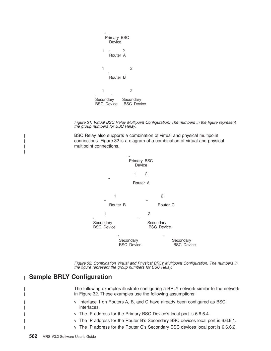
. These examples use the following assumptions
Sample Brly Conguration
Multipoint connections
IP address for the Primary BSC Devices local port is
Group
Brly Considerations
When conguring BRLY, keep the following in mind
Remote
Reduce the total network throughput
Devices that disconnect frequently
MRS V3.2 Software Users Guide
Conguring and Monitoring BSC Relay
BSC Relay Conguration Commands
567
Group type
Default value multipoint
Conguring and Monitoring BSC Relay
Local-port
Valid values X01 to XFF
Default value S
Station Address Character
Remote group number
Local±port group#
Default value local
Local or Remote
List for network BSC
Number of pairs of SYNs
List for protocol Brly
Link EOT
Remote Group
Cable
Use the set command to congure the BSC interface parameters
Displays the conguration of a specied group
Code ebcdic or ascii
Default value mark Speed bps
Accessing the BSC Relay Monitoring Environment
Default value yes Frame-size
Eotlink yes or no
BSC Relay Monitoring Commands
Syntax Clear Example
Command are erased
Router, the effects of this command are erased
Remote port
Packets Forwarded
Local Group
Station Address
Packets Discarded
BSC Relay Interfaces and the Gwcon Interface Command
Gwcon Talk 5 and Commands
Adding V.25bis Addresses
Using the V.25bis Network Interface
579
Set command-delay-timeoutcommand species the amount of time
Using V.25bis
Timeout-no-answer commands
Conguring the V.25bis Interface
Adding Dial Circuits
Configadd device dial-circuit
Conguring Dial Circuits
Circuit Configset selftest-delay
583
25bis Conguration Commands
Conguring and Monitoring the V.25bis Network Interface
V.25bis conguration prompt now displays on the console
Local Network Address
25bis Conguration Commands
Local Network Address Name
Non-responding addresses Retries
Command-delay-timeout # of milliseconds
Call timeouts
Command Delay
Connect-timeout # of seconds
Valid values NRZ or Nrzi Default value NRZ Hdlc speed
Disconnect-timeout # of seconds
Hdlc encoding
Timeout-no-answer # of seconds
25bis Monitoring Commands
Add v25-bis-address command
Local-address address name
Syntax calls Example
25bis Operating Commands
Calls
Site Name
Circuits
Network dial address of the local port
Call timeouts Command Delay
Network address name of the local port
Syntax Statistics Example
Common names for the circuits
Type of adapter cable being used
Circuit numbers as identied by V.24 specications
Transmit clock speed approximate
25bis and the Gwcon Commands
Statistics for V.25bis Interfaces and Dial Circuits
Type of adapter cable that is being used
Vec Self-Test Passed
Interface
CRC error
Adding V.34 Addresses
Using the V.34 Network Interface
595
Conguring the V.34 Interface
Using
These commands, see ªV.34 Conguration Commandsº on
Optional V.34 Parameters
Using V.34
Circuit Configset selftest-delay
V.34 conguration prompt now displays on the console
Conguring and Monitoring the V.34 Network Interface
599
Devices
34 Conguration Commands Summary
Conguring
Initialization string
Command strings sent to the attached modem
Modem strings
Modem-init-string
Add v34-address command Modem-init-string value
Speed # bits per second
Monitoring Function Command
34 Monitoring Command Summary
Network address name of the dial circuit
Circuits
Syntax Parameters
Example parameters
CRC
Statistics for V.34 Interfaces and Dial Circuits
Example interface
Nicknames
Conguring
Isdn Adapters and Interfaces
Using the Isdn Interface
Isdn Overview
611
Using Isdn
Dial Circuits
Oversubscribing and Circuit Contention
Addressing
Caller ID and Lids
Cost Control Over Demand Circuits
Isdn Cause Codes
Isdn Q.931 Cause Codes
Code Cause
Frame Relay over Isdn Conguration
Sample Isdn Congurations
Following topics show several typical Isdn congurations
Channelized T1/E1
Isdn Configset switch chan
WAN Restoral Conguration
Example of conguring a Channelized T1 interface
Requirements and Restrictions for Isdn Interfaces Router
Switches/Services Supported
Switch names Valid command
7set timeslot 2
Isdn Interface Restrictions
You cannot boot or dump the router over an Isdn interface
Setting up and taking down B-channel connections
Dial Circuit Conguration Requirements
Isdn Config set local-address-name
Configadd isdn-address
Isdn Configset switch net5
Conguring Isdn Parameters
Value from 0 to 63, assigned by your provider
TEI number of your Isdn switch
Optional Isdn Parameters
D-channel. For example
T1/J1 PRI Interface
Default is ANSI-T1.403 For example
Conguring the Isdn Interface
E1 PRI Interface
Use the set calls command. For example
This section describes how to congure a dial circuit
Isdn-address command. For example
Specify the timeout period for the circuit
Which is the destination name by specifying a lidoutaddr
Using ªADD ISDN-ADDRESSº at thecong prompt
Use the encapsulator command. For example
Prevent initial packets from being dropped. For example
Native I.430 Support
Isdn I.430 and I.431 Switch Variants
Native I.431 Support
Default value is none
Support
Block-Calls
Isdn Conguration Commands
Conguring and Monitoring the Isdn Interface
627
Syntax Disable Ps1
Isdn Conguration Commands
Syntax Enable Ps1
Framesize 1024 or 2048 or 4096 or
Default Value Disabled
Default Value a
Default Values B8ZS
Frame-type
Default ValueDisabled Local-address-name address name
Default Value ANSI-T1.403 For E1 PRI
Default Value HDB3
Default Value None Example
Timeout-call-address. It is xed at
Service-prole-id B-channel# spid#
Timeout-call-address # of seconds
Default Value 180 seconds
Dn1 directory number
Default Value Dmspri
Dn0 directory number
Tei auto or none or value
Syntax Cause code
Cause Code
Example add FF
Monitoring Command Function
Isdn Monitoring Commands
Isdn Monitoring Command Summary
Syntax cause code remove value
Channels
Isdn Monitoring Commands
Syntax Channels
Rmt Disc
MAC/Data-Link
NnnData
Opr Req
L2Counters
Dial-dump
L3Counters
Example for PRI with E1
Example for BRI using
Syntax statistics Example for BRI
Statistics
Example for PRI with T1 using
Example for Channelized T1
Isdn and the Gwcon Commands
Isdn and the Gwcon Commands
Circuits Be dropped and re-dialed
Conguration Information on Router Hardware and Software
Conguring and Monitoring Dial Circuits
Dial Circuit Conguration Commands
643
Inbound destination
Conguring Dial Circuits
Nbound destination
For Frame Relay, enter set data-link frame-relay
Be shown for all interface types
Variantsº on
Any inbound
Base net
SelfTest Delay Timer
Bandwidth
Callback
Anyinbound
Bandwidth kbps
Callback Yes or No
V34-address command
Default value 7E
Destination addressname
Lidoutaddr addressname
Lidused enabled or disabled
Selftest-delay# of milliseconds
Timeslot list of slots
Callback
Dial Circuit Monitoring Commands
Syntax Callback
Appendix A. Quick Conguration Reference
Conguring LAN Emulation
IPX DNA
Conguring Interfaces
Ethernet
Token-Ring
Conguring Multilink PPP MP Interfaces
Lidin
Conguring Dial-Circuits
Add another Dial Circuit Yes, No Yes No
Next, the following prompt will be shown
Default is 30 minutes
Be used for the duration of the connection
Dialoutserver
Conguring Bridging
Conguring Protocols
Panel similar to the following is displayed
Conguring IP
Conguring IPX
Following prompt is displayed
Token-Ringor Ethernet
Conguring IPX for Token-Ring
End stations
Following prompts are displayed
Ipxwan is enabled on any network interfaces
Which to build a host number
Highest Node Number
Conguring DECnet DNA
Router Level
Highest Area
DNA Configuration Saved
Tftp Boot
Bootp Boot
Enabling Console Modem-Control
IBD Boot
Restarting the Router
Appendix A. Quick Conguration Reference
MRS V3.2 Software Users Guide
GTE-Telenet
Appendix B. X.25 National Personalities
675
MRS V3.2 Software Users Guide
Assembling a Load File Under Unix
Appendix C. Making a Router Load File from Multiple Disks
Assembling a Load File Under DOS
677
Disassembling a Load File Under DOS
Resulting le gw.ldc is the assembled router load
# ls -la total
Disassembling a Load File Under Unix
# cutup gw.ldc gw # ls -la
MRS V3.2 Software Users Guide
List of Abbreviations
681
Cgwcon
Eth
DoD
Dtype
Fa-ga
InARP
Ifc#
Kbps
LSrxl
NetBIOS
LSreq
Mbps
Ring error monitor
Network Service Access Point
Random access memory
Ring indicator routing information
Rxmits
ROpcon
Rtype
Rxmt
252
251
253
List of Abbreviations
MRS V3.2 Software Users Guide
Glossary
691
Advanced Peer-to-Peer Networking Appn
Advanced Peer-to-Peer Networking APPN. An
Advanced Peer-to-Peer Networking Appn end
Advanced Peer-to-Peer Networking Appn network
Glossary
Carrier sense multiple access with collision
Signal detector Rlsd
Control point management services CPMS. a
Control point management services unit CP-MSU
Congestion. See network congestion
Data circuit-terminating equipment DCE. In a data
Digital Network Architecture DNA. The model for
Explorer frame. See explorer packet
Level
Fragment. See fragmentation
General data stream GDS. The data stream used for
International Organization for Standardization
Integrated services digital network ISDN. a digital
Integrated Digital Network Exchange IDNX. a
International Telecommunication Union ITU.
Inverse Address Resolution Protocol InARP.
Management interface LMI protocol
Line switching. Synonym for circuit switching
Local management interface LMI. See local
Local management interface LMI protocol. In NCP
Glossary
MRS V3.2 Software Users Guide
Non-Return-to-Zero Changes-on-Ones Recording
Open Systems Interconnection OSI reference
Packet mode operation. Synonym for packet
Switching
Rapid Transport Protocol RTP connection.
Ring. See ring network
Routing Table Maintenance Protocol RTMP.
Simple Network Management Protocol SNMP.
Subnetwork mask. Synonym for address mask
Subnetwork Access Protocol SNAP. In LANs, a
Subnet mask. Synonym for address mask
Synchronous Data Link Control Sdlc a
Glossary
Transmission Control Protocol/Internet Protocol
Wildcard character. Synonym for pattern-matching
Character
MRS V3.2 Software Users Guide
Index Numerics
715
Binary synchronous communications relay Brly
Chap
Opcon
DOS
PAP
Lter
SVC FRF
MRS V3.2 Software Users Guide
Gwcon
BUS
List list
MS-CHAP
Ospf
Config Gwcon
Messages containing IP addresses 162
387 Technical support access
Unix
XTP
How satised are you that the information in this book is
Readers Comments Ð Wed Like to Hear from You
Please tell us how we can improve this book
Readers Comments Ð Wed Like to Hear from You
SC30-3681-08
Page
Ibmr
IBM