NEC America, Inc
Liability Disclaimer
NEAX2400 IMX
Revision Sheet 2/7
Revision Sheet 3/7
Revision Sheet 4/7
Revision Sheet 5/7
Revision Sheet 6/7
Revision Sheet 7/7
CallCenterWorX-Enterprise ACD System Manual
NEAX2400 IMX
Table of Contents
Table of Contents
Asyd
Acdhs
450
List of Figures
List of Figures
List of Tables
This page is for your notes
Introduction
Some information for commands used with the ACD System
Circuit Card Manual
Located in this manual
General Information
System Specifications
General Information Functional Outline
General Information System Configuration
MIS
CPU
ELC
PA-16ELCJ
Block Diagram of ACD System Dual CPU Configuration
General Information System Capacity
Data Transmission Speed Mbps
Physical Interface
Communication protocol
TCP/IP
4shows the outer view of Dterm Series III Agent Position
Mm ⋅ 223.7 D mm
Over View of Dterm Series E Agent Position
General Information Supervisory Position
This section defines ACD-related terms
Glossary of Terms
ACD Group Configuration NDA-24282
General Information
Concept of Operation Mode
General Information
Contents Static Sensitive Handling Precautions Required
Installation
Installation
Installation Procedures
Connector leads A0 and B0
NAP-200-101 Sheet 2/3 Installation of ACD Agent Position
Key Pads on ACD Agent Position Keyboard Dterm Series E
Leads A0
Key Pads on Supervisory Position Keyboard Dterm Series
Key Pads on Supervisory Position Keyboard Dterm Series E
10 Cable Connection between MIS and PBX
Confirming the amplifiers current drain
13 Connection of Announcement Machine
14 System Configuration when IVR/Host is installed
15shows the cable connection between Host and the PBX
16shows the cable connection between IVR and the PBX
PROGRAM=LOAD System DATA=LOAD
System START-UP Procedure for Adding ACD Features
Installation
INDEX864
Asyd SYS1
Asydl SYS1 INDEX512
INDEX513
Upgrading ACD System from NEAX2400 ICS to NEAX2400 IMX
MIS IBMPC/AT
MAT IBMPC/AT
Installation Upgrading Procedure
This page is for your notes
Switch Setting of ACD Circuit Cards
Explanation of ACD Circuit Cards
PA-CP53 CPU
When this circuit card is mounted in Pimb
Lana
CPU OPE
Clka
Copa
Sense
Reset Push
MBR
Down
SW2 OFF
SW2
Reset Sense SW0
PIM
SW1
PH-PC22 Eapi
LPRJ-A CPRAC-0 CPRAC-1
OPE/MB
Iocope
Clkalm
ACD-MIS
LPRJ-A SW0
Lcma
PH-PC27 Eapi
PH-PC27 LPRJ-A CPRAC-0 CPRAC-1
Circuit card make idle
To 7 bit Sets the non-protocol RS-232C port data length
SW10 For Port SW11 SW12 MIS Port Interface
SW12 5, 6 on only
UP Circuit card make busy
SW10 5, 6 on only
SW11 5, 6 on only
PA-AL16 Almc
SW1 SW5 SW4
Down Cpusel Middle
For Acdp Dual System Configuration
For Acdp Single System Configuration
Emasup
SW6 OFF
Alarm Bus Fixed
SW4 OFF
SW5
SW6
Emasup Cpusel
SW0 SW1
SW2 SW4
PH-PC21 Apint
Down
Acdp of dual-system configuration
When using this circuit card in the Acdp
Single-system configuration or when
Connecting this circuit card to No system
LPRJ-A
PA-PC56-A Copy
OPE
OFF SW0
Sreq
OFF = System No
APM-A\E
Sreq SW0
On = System No
PA-CP54 CPU
COP ALM
CLK ALM
For MMG ICS, UMG ICS, UMGx
Normal Setting
When connecting the ACD System to
When the data memory of Acdp is to be
Memory Alarm NMI not inhibited
Memory Parity Alarm Inhibited
Memory Parity Alarm not inhibited
Memory Alarm NMI inhibited
SW3
RAM
SW4 OFF
OFF = PA-ME34 Not Mounted
APM MBR
On = IMX Systems
On = PA-ME34 Mounted
PA-ME34 Cram
Dmwd
Sets the RAM area to
Data memory area write enable
Dmwdk
Data memory area write inhibited
APM-A\E Dmwdk SW0
PA-IO02-A IOC
Green Remains lit while Port 0 is in on-line state
On LINE1
Green Remains lit while Port 1 is in on-line state
On LINE0
OFF SW3
Setting is inhibited
MB REQ
OFF Line
Stop Bit 1 bits
Is disabled
Data Length 7 bits
Data Length 8 bits
CD signal lead is not to be used to the port
PB terminal becomes plus + when the port
DR signal lead is not to be used to the port
DR signal lead is to be used to the port
RS Connector Leads Accommodation
SW02
OFF Line SW0
PH-BS16 PBI
ACT OPE Pwralm Eqby Pbih Pbil OPE0 OPE1 TR BSY RV BSY
OPE0
ACT
Pwralm
Eqby
Pbil
Pbih
Switch Setting Sheet
PA-GT17 Spgt
Miscme Spgt
SW10
Miscme SW0
Switch Setting Sheet
PA-16ELCDD ELC
PIMU-A
BL0
When not connecting Dterm 24 key type to this
For using this circuit card as 8DLC
For using this circuit card as 16ELC
When connecting Dterm 24 key type to this
LT Connector Leads Accommodation of PIMU-A 1/2 NDA-24282
LT Connector Leads Accommodation of PIMU-A 2/2
LT Connector Leads Accommodation of Pimb 1/2
LT Connector Leads Accommodation of Pimb 2/2
ELC Connector Leads Accommodation of Pimb 1/2 NDA-24282
ELC Connector Leads Accommodation of Pimb 2/2
Connection Diagram
Connection Diagram
PIMU-A
PA-16ELCH 16ELC
PIMU-A
Green Remains lit while on-line operations are normal
Off when on-line operations are abnormal
Off when all the power supply circuits are normal
Off when the corresponding circuit is idle
Single Port Mode
When APR-J/APA-J is not connected
When APR-J/APA-J is connected
Setting of Speech Level NEAX2400 IMS
OFF
LT Connector Leads Accommodation of PIMU-A 1
LT Connector Leads Accommodation of PIMU-A 2
LT Connector Leads Accommodation of PIMU-A 3
When the mode is 8DLC Mode/Dual Port Mode
LT Connector Leads Accommodation of Pimb 1 NDA-24282
LT Connector Leads Accommodation of Pimb 2
LT1,3, 5, 8, 10 Connector
When the mode is 8DLC Mode and the APR-J/APA-J is used
Connecting Route Diagram
PIMU-A SW0
PA-16ELCJ 16ELC
When this circuit card is mounted in Pimk
Palm
Fixed on
SW01 Fixed in the system
SW00 Circuit card make busy
10 LT Connector Leads Accommodation of PIMU-A 1
10 LT Connector Lead Accommodation of PIMU-A 2 NDA-24282 E
10 LT Connector Leads Accommodation of PIMU-A 3
11 LT Connector Leads Accommodation of Pimk 1 NDA-24282 E
11 LT Connector Leads Accommodation of Pimk 2
11 LT Connector Leads Accommodation of Pimk 3 NDA-24282 E
Module Slot no Switch Name Switch Shape Remarks
PA-4DATA 4DAT
Pimb
BL3
BL4
BL7
Through No
Cuit No
When using as announcement equipment only
MB SW11 Circuit card make busy
SW2 for Cir
SW7 OFF
SW8
Start KEY
Mode
Circuit No make busy request cancel
SW12 Recording from a tape recorder. Write
WR KEY
12 LT Connector Leads Accommodation of PIMU-A NDA-24282 E
13 LT Connector Leads Accommodation of Pimb
SW7 SW8 SW9
PIM SW1 SW2 SW3 SW4 SW5 SW6
Down
PA-4DATB DAT
Pime
State or has not been assigned in the system
Mrcs
MB RQ
To be used as announcement equipment
Compression Law ∝ -law
Compression Law A-law
To be used as external hold tone source
Start
SW7
15 LT Connector Lead Accommodation PIMU-A NDA-24282 E
16 LT Connector Lead Accommodation Pime
SW4 SW5
PA-4DATB DAT
PA-4DTLA 4DTL
Rfbs Ecsl Sfbs Rsbs SW0 OPE N-OPE BL3 BL2 BL1 BL0 SW1
Ecsl
Rfbs
Sfbs
Rsbs
17 LT Connector Leads Accommodation of PIMU-A 1/2
PA-4DTLA 4DTL
18 LT Connector Leads Accommodation of Pimb 1/2
18 LT Connector Leads Accommodation of Pimb 2/2 NDA-24282 E
MDF NEAX2400 IMS
PA-CC98 Ether
When mounting in the Pimb
Case of module type
ERR
Sets 0, corresponding to bit 1 of MAC address
DIP Switches
Sets 0, corresponding to bit 0 of MAC address
Sets 1, corresponding to bit 0 of MAC address
Rotary SW
= Fixed not used Fixed setting When operating
SW1 Sets 0, corresponding to bit 11 of MAC address
Sets 1, corresponding to bit 11 of MAC address
Fixed for the system
Circuit Card Mounting Locations/Conditions
PA-GT16 MBB
LAN ALM
Mbrq
SEG
Xfffffh
APM Mbrq
Down Circuit card make-busy cancel
Circuit card in operating
Status
This page is for your notes
Basic Office Data Assignment
Office Data Design
Pattern
Design of UCD station
Back-up UCD for Fusion service
ICT
ICT Link Down
Office Data Design
Office Data Design ACD in a Fusion Network Data Assignment
Acdlog
Acdana
Acdccv
Acdivr
Ccvact
Available
Examples
Data Programming
Office Data Design Multiple Acdps in a Fusion Network
Service Conditions
IMX-U Acdp
→ * See Note 2 in Legend
Only
Fusion Network with Multiple ACDPs Example
Network Configuration of ACD systems NDA-24282 E
Asydl SYS1, INDEX865
FPC no. of the node providing Acdp
PBX Asydl SYS1, INDEX866
Asydn SYS1, INDEX533
Aokc
Amno
Acno
Aadt
Office Data Design
ACD Service Feature
Feature Code Service Name
Feature Code Service Name
None
31A Abandoned Call Search ACD
34A Assistance ACD Agent ACD
Assistance ACD Agent ACD
35A Automatic Answer ACD
Automatic Answer ACD
37A Availability ACD Position ACD
Acdspl Auto Ready After Call
Myline
80A Announcements ACD
AADT/AADTN Acdccv
85A Agent Personal Queue ACD
Agent Personal Queue ACD Operating Procedure
Individual call
Means an announcement service is out of service for an
Announcement Number
Announcement number for an individual call
86A Auto Work Mode for PBX Calls ACD
91A Analog ACD Position ACD
ANT
Acdana ACC
Code
Type
Acdspl Night
93A Alternate Night CCV ACD
133A Agent Anywhere ACD
Asydn
Asydl
20A Break Mode ACD
Adyd Assign Break key to function key
Adyd Assign Trktrbl to function key
21A BAD Call Notifications ACD
35A Call Distribution to Agents ACD
Call Distribution to Agents ACD Operating Procedure
67A Call Transfer to Split Queue ACD
None
68A Call Waiting Indication LCD DISPLAY/CW Lamp ACD
70A Calling Party Identification ACD
Calling Party Identification ACD
108A Call Control Vector ACD
ETA
Ivrdn
Call Control Vector ACD
Call Control Vector ACD
Hang UP
Blank
ETA less than 11 seconds will be considered as 0 second
Operating Procedure
Refer to Assignment of ACD CCV Data in Chapter
110A Call Waiting Lamp with Chime ACD
127A Call Forwarding Split ACD
Call Forwarding Split ACD
191A Call Recover ACD
199A Connection Displays ACD
= number of seconds to display 3 thru 9 seconds, or 0 for
Setup the display sequence and timing for the current agent
= single-digit display code 3 thru
DD = double-digit display code 10 thru
Connection Displays ACD Service Conditions
Queue to Split Pause Announcement Conditional Queue to Split
133A do not Disturb Split ACD
Do not Disturb Split ACD
6A EMERGENCY/RECORDER ACD
EMERGENCY/RECORDER ACD Service Conditions
TCL = 4 Tie Line/Announcement Trunk
CDN2
Onsg = 2 PB, 60 msec. interval
CDN6
Trunk number for recording machine
Aadtn Assign the related data of recording machine
Recording Trunk
Route number for recording machine
10A Function Groups Splits ACD
Preference level
25A Flexible ID Codes ACD
Priority
Priority for the split assigned in Split 1-250 or Agent’s
Flexible ID Codes ACD Service Conditions
See Time of Day/Week Routing ACD T-50A
20A Holiday Scheduling ACD
31A HOT Split ACD
HOT Split ACD Programming
99A Infolink Data Messages ACD
Announcement Request
Dialed digits
Manage Call
Split Status/Caller Status Request
Port
Asdt
STN
TEC
19A LOGON/LOGOFF Position ACD
Digits maximum
Logon ID
48A Language Default ACD
92A Logoff Warning ACD
28A Monitoring ACD Supervisor ACD
Monitoring ACD Supervisor ACD
Akyd Assign MON/BARGE function to a feature key
SYS1, INDEX93
29A Multiple Customer Groups ACD
No manual operation is required
SYS1, INDEX92
Name
Default Lauguage
Operator Access Code
SYS1, INDEX94
79A Multiple Supervisor Groups Splits ACD
Multiple Supervisor Groups Splits ACD Programming
88A MIS Operator Selection ACD
Acdtn OPE no Operator access code Maximum 5 digits
89A Monitor ME ACD
KYN =
As an example
KYI = FKY = Assist
90A MULTI-SPLIT Agent ACD
MULTI-SPLIT Agent ACD
Any Split
Acdlog
12A Night Service ACD
Acdplt Alternate Night CCV
Index
Step
14A NON-ACD Call ACD
10A Overflow ACD
19A Overflow Outside ACD
21A Priority Queuing ACD
Highest Priority Callers Always GO First
Determining Trunk Caller Priority
Priority Queuing ACD Programming
40A Pilot Numbers ACD
45A Personal Emergency and Assist ACD
Personal Emergency and Assist ACD
1A Queuing ACD
This feature is implemented through the programming of CCVs
Queuing ACD Service Conditions
19A Release ACD Position ACD
Akyd Assign Release function to a feature key
CCV Action Ring Delay Argument 1-15 seconds
145A Ring Delay ACD
91A Splits ACD
After ACD Call Mode
Assist Destination
Do Not Disturb Mode
Every position in the ACD may be a member of the same split
Stranded Calls CCV
97A Split Display ACD Position ACD
98A Split Selection ACD
108A Stranded Call Routing ACD
There is no LED indication when the TRK Trbl key is pressed
Akyd Assign TRK Trbl function to feature key
24A Trunk Trouble Report MIS ACD
49A Tally Count ACD
50A Time of DAY/WEEK Routing ACD
51A TALLY-OH Codes ACD
006# ACD call Sample Displays
007# Exits Work mode Sample Displays
To 3 digits
005# On an ACD call Sample Displays
Display time of longest waiting caller for a given split
Vacant, Work, Break, Ready, or on an ACD call
Display number of agents on break for a given split
Change Night mode of a given split
Turn Bad Call Notification MAT print-outs on or off
Require Tally Per Call
85A Tally Required ACD
Variable Queueing
After Call Work Mode Timeout
5A Work Mode ACD
Acdspl Work Mode Restricted
Work mode timer timeout 0-9999 sec
6A Work Mode Time Limit ACD
1A ZIP Tone ACD
ACD Service Features Functional Test Procedures
Call Distribution to Agents C35
Announcements A80
Availability-ACD Position After Call Work A37
Break Mode B21
Overflow Outside-ACD O19
Emergency/Recorder E6
END
Abandoned Call Search
Abandoned Call Search A31 Trunk Trouble Report
Trunk Trouble Report-MIS T24 MIS Terminal Functions
NAP-215-101 Sheet 1/2 ACD Incoming
NAP-215-101 Sheet 2/2 ACD Incoming
NAP-215-102 Sheet 1/1 Call Distribution to Agents
NAP-215-103 Sheet 1/1 Priority Processing
NAP-215-104 Sheet 1/1
Related commands AADT, Acdccv
To station B
If the weekly schedule No. is set as the incoming path
Trunk call origination
Place a C.O. trunk call from station a
NAP-215-107 Sheet 1/1 Overflow
NAP-215-108 Sheet 1/1 Emergency Recorder
NAP-215-109 Sheet 1/1 After Call Work Manual
After
NAP-215-111
NAP-215-112 Sheet 1/1 Auxiliary Work
NAP-215-113 Sheet 1/1 Monitoring-ACD Supervisor
NAP-215-114 Sheet 1/2
NAP-215-114 Sheet 2/2 Night Service
NAP-215-115 Sheet 1/1 Abandoned Call Search
NAP-215-116 Sheet 1/1 Trunk Trouble Report
This page is for your notes
For ACD commands, see .2,ACD Commands in this chapter
PBX and ACD Command Programming
Data
Asyd Assignment of System Data
SYS
SYS Index
= Out/In Service
ACD in Service Fixed Data
= In service 1 = Out of service
Tcfi timer 0 0 = 2 sec. interval
= ACD In Service 1 = ACD Out of Service
ACD Announcement service 0/1=Out of service/In
Service. Note
OAI/ACD Service Note
=Out of Service 1=In Service
CPU ACT/ST-BY Change Function
Acdp No System Mounting Status Indication
Asydl command is comprised with System Data-1, Index
Asydl Assignment of System Data into Local DM LDM
Refer to the programming sheet in the following pages
518
Default Gateway Address of External LAN
525 Example Default Gateway Address
LDM Local Data Memory usage. Assign data 1
FPC of the node providing IP
Assign 0 when the ACD service is activated in the self node
B4 = 0, b5 = 0 2 ports
B4 = 1, b5 = 0 8 ports
533 FPC number of the node that has the standard Vndm
Asydn Assignment of System Data in NDM
Network Data Memory NDM usage. Assign data 1
514
NND
Aokc Assignment of OAI Key Code
Kind
Tone
Trbl
SFC
Asdt Assignment of Station Data
Lens
RSC
System Data Programming Sheet
RES
Asfc Assignment of Service Feature Restriction Class Data
DAY/NIGHT
SFI
Service Feature Restriction Class Data Programming Sheet
Akyd Assignment of Key Data for Dterm
Plstn
PRI
LN PRE
Pltn
No Ringing Sec Not used 30 sec 20 sec 10 sec
FKY
Speaker
Answer Feature
Conference Redial
Transfer Recall Hold
Dterm Key Data Programming Sheet 1/2
Dterm Key Data Programming Sheet 2/2
UCD
Amno Assignment of Monitored Number
MNO
NMI
Chapter
Lnmi
Amnol Assignment of Monitored Number for LDM
UGN
Lmno
Chapter
Nnmi
Amnon Assignment of Monitored Number for NDM
Nmno
NEAX2400 IMX
Chapter
Acno Assignment of Conversion Number Data
Route Number Must be Ring Down Trunk
Monitored Number as programmed in Amno
Route Number Tenant Number Monitored Number MNO
Acnol Assignment of Conversion Number Data for LDM
Lgrt
Logical Route Number 1-254 Must be Ring Down Trunk
Chapter
Acnon Assignment of Conversion Number Data for NDM
Chapter
CNT
Aadt Assignment of Announcement/Dictation Trunks
Msgt
Wait
ANT ANT/DCT Number Type
Availability of Disconnect Timer Available for Type = ANT
Aadtn Assignment of Announcement/Dictation Trunks for NDM
Logical Route Number 1 ~
ANT/DCT Type Number
General
Algnn Assignment of Telephone Number Data for NDM
Data Sheet
Algsn Assignment of Telephone Station Data for NDM
User Tenant
Lens is used to specify the Telephone number Type =
STN is used to specify the Telephone number Type =
Acdtn
System
Total ACD
Acdccv R, Acdplt R
Amno R, Acno O Acnon O, Aefr R
PBX and ACD Command Programming Setting UP the ACD
IMX ACD MAT
Acdtn Assignment of ACD Tenant Data
Port Assignment
Default Language
Answer Timer
Tenant Number
Start Asyd Acdtn Description
END Start Acdtn Description
Delete the Tenant data
Ivrno
Acdspl Assignment of ACD Split Data
Acdspl Assignment of ACD Split Data
Acdspl Assignment of ACD Split Data
Call Recover Time
Stranded Call CCV
HOT Split
Remove the Split data
Start Description Acdtn
Assign the Split data
END Start Description Acdspl
Acdlog Assignment of ACD Receiver ID Code
Chime
Login ID
Language
MULTI-SPLIT
Remove the ACD agent logon ID code
Start Description Acdlog
Assign the agent logon ID code range 1 to
END Start Description Acdlog
Acdpsn Assignment of ACD Position Data
Split Assignment
ACDPSN, ALL
Position Number
ACD Number
Assign the key data for the ACD position
Start Description
Assign the station numbers for the ACD line and the PBX
Line
Acdccv Assignment of ACD CCV Data
Call Control Vectors Tenant Number
Argument
Tenant Number CCV Index CCV Step CCV Action
Digits
IVR Access number maximum
Assigning and Removing Call Control Vectors
Start AADT/AADTN Asdt Acdplt Acdspl Acdccv END Description
Acdplt Assignment of ACD Monitor Number
Internal
Pilot Number
Route to
Priority Trunk
Acdtg Assignment of ACD Trunk Group Data
Trunk Group
TRK
Remove the trunk group data
Start Description Acdtg
Assign the trunks as ACD circuits
END Start Description Acdtg
Break Type
Acdana Assignment of ACD Analog Split Access Code
Access Code
Tally Code
Announcement upon failed operation
Success
Announcement upon successful operation
Failure
Acdivr Assignment of ACD IVR Data
Tenant
IVR port number associated with this directory number
IVR
Minute
Acdhs Assignment of ACD Holiday Schedule
Schedule
Start Time Hour
Start Description Acdws
Acdhc
END Start Description Acdhs
Hour Minute Chapter
Acdhc Assignment of ACD Holiday Calendar
Month
DAY
Assign the Holiday Calendar
END Start Acdhc Description
Remove the Holiday Calendar
Month DAY NDA-24282CHAPTER
CCV start time minute
Acdws Assignment of ACD Week Schedule
Sun, Mon, Tue, Wed, Thu, Fri, Sat
CCV start time hour
10 Assigning and Removing Week Schedule Information
Start Acdplt Acdccv Acdws END Description
Week
Programming
Acdcom ACD Communications Data
System Information
User Settings
System Tenants 1 ~
Time Out Settings
System Information
For External ACD
ACD Backup
IT S E S S IO N
This page is for your notes
System Operations
Operation of Dterm Agent POSITION/SUPERVISORY Position
When ID Code is not Required
ACD Call Manual Answer Mode
System Operations Work Mode
Set/Reset when idle
Set/reset in Work Mode
From Night mode to Day mode
System Operations Assistance
ACD System Restart Processing
Fault Recovery Procedure MIS
System Maintenance
Maintenance
Fault Diagnostics
Bad Call Notification 26-V LAN Interface Error Report
TCP/IP Link Failure
ACD-MIS Lock UP
Index 42, b2 =
MIS has locked up. To be displayed when Asyd command, SYS
Ether + TCP/IP
System Message 4 R
NEC ESD
03 = Ether + TCP/IP
~ 8 IP address
60030
MAY 11
System Message 5 Q ACD-MIS Lock UP NEC ESD
AUG 14
System Message 6 H BAD Call Notification NEC ESD
NDA-24282 E Revision
Bad Call Notification Codes
Supervisor 3888 used Tally-Oh code to force logoff of agent
Agent 78300 used Tally-Oh code to forcibly logoff
Attendant 2 called pilot number 4350 without a held party
20 29 43 A1 00 00 45 58 AA 00 00 00 17 00
1930
System Message 26 LAN Interface Error Report NEC ESD July
Fault Diagnostics
ACD MIS Lock UP
Shown inside Diagnostics procedures
Host is out of order. Repair the Host computer
When Message, 26-V is displayed
System Operations and Maintenance Manual
Host is still in abnormal status?
Fault Recovery Procedure
System Maintenance MIS Fault Recovery Procedures
IVR
Appendix a Glossary
Acdp
ACD MAT
MAT
Maintenance Administration Terminal
CCV
Appendix B Field Values for ACD Screens
PBX
Action Argument Description
MM/DD
Hhmm
None Optional Digits Number
Number. Options are Index CCV index and step number
Splits Designates what splits are allowed All, or up
CCV list To be followed
None Optional Index Step Number
Table B-1 Field Values for ACD Screens 8/8
Available, ⋅ Not available, Not applicable
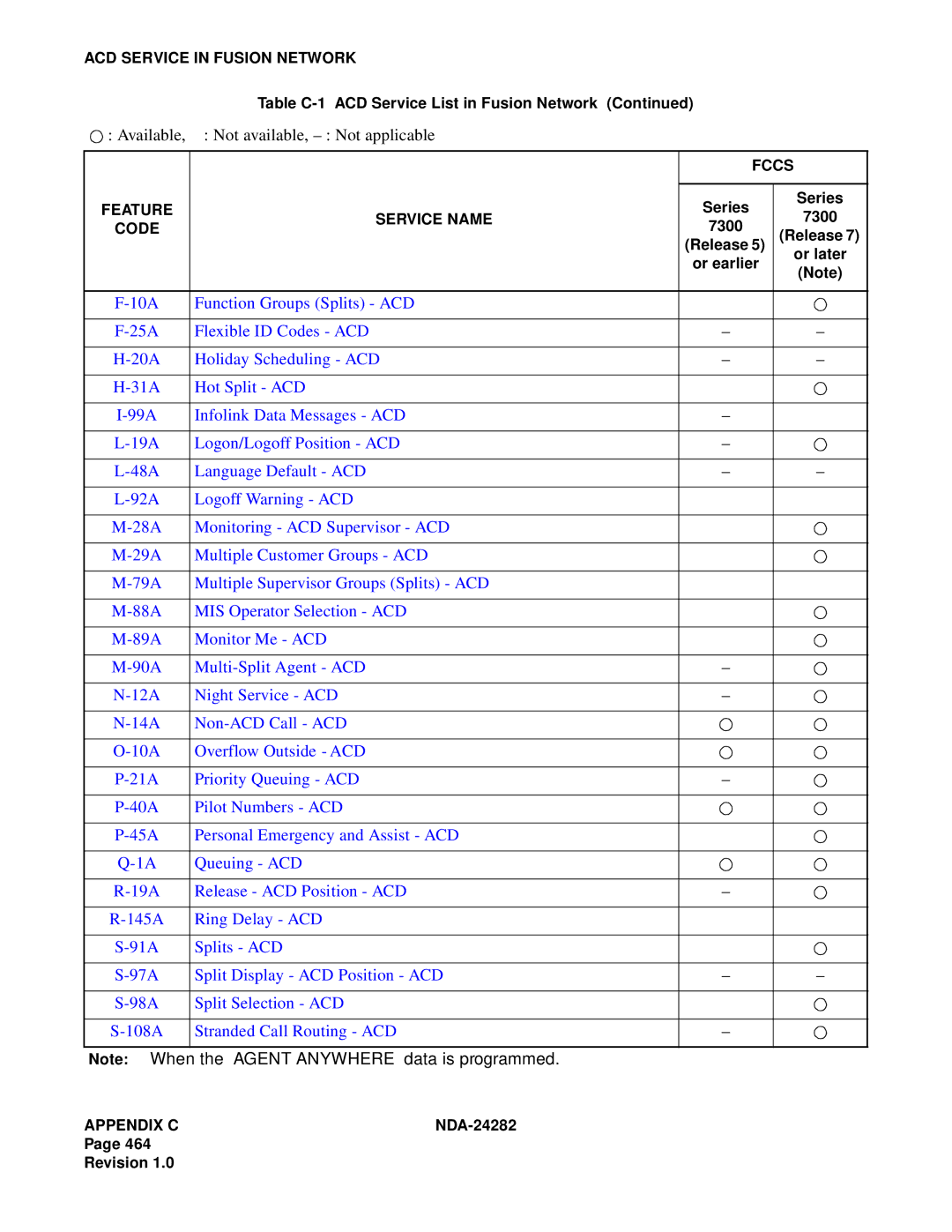
Appendix C ACD Service in Fusion Network
ACD Service in Fusion Network
NDA-24282APPENDIX C
This page is for your notes

 : Available, ⋅ : Not available,