Cut Sheet Printers Maintenance Manual Models C30 and C30D
Trademarks
Printing History
Conventions
Preface
Using This Manual
Other Manuals
Page
Contents
Viii
Print Quality Samples
Diagnostic Tests
Wiring Diagrams and Electrical Data
Removal/Replacement Procedures
Xii
Options
General Printer Maintenance
Abbreviations and Acronyms
Every-Call Cleaning Procedure
Printer Troubleshooting Overview
Printing and Troubleshooting Overview
Receiving data
Theory of Operation
Host
Paper Path and Cycle Sequence
Simplex Printing
Duplex Printing
Paper Path
Paper
Error Code Technical Definitions
Error Code Technical Definitions Type Description
Path
Fuser
OPC
Assembly
Controller Errors
Sensor and Switch Locations
Top view Front view Developer right view Developer left view
Right side view Top left, duplex tray view Front view
Sensor and Switch List Sensor/Switch Name
General Troubleshooting Tips
Troubleshooting Overview
Problem Printer or Host?
Protocol Converters
Reading the Error Log
Confirming Line Power
Did only the Ready light come on with no numeric display?
Using the Troubleshooting Analysis Guide TAG
TAG 001 Troubleshooting a Problem
Sample TAG
Options reviews printer options HCI, HCO information
Standard Procedures
Power-on-reset POR
Checking Continuity
Installing the Interlock By-pass Tool
Producing a Developed Image
Producing a Toner Patch
Producing a Toner Patch on the Photoconductor Unit
Completing a Service Call
Drive Indication Display
Clearing the Error Log
TAG Cross- Reference Tables
TAG Cross-Reference Tables
Printer Error Codes Printer Error Code Meaning Go to TAG
Error Code/TAG Cross-Reference
PCL Error Codes PCL Error Code Meaning Go to TAG
PCL Error Codes PCL Error Code Meaning Go to TAG
Code
IGS Firmware Error Codes IGS Firmware Error Code Meaning
PCL Failure Error Codes
IGS Software Error Codes
TAG Cross- Reference Tables
TAG Cross- Reference Tables
11. Blank Print TAGs Blank Prints Go to TAG
Print Quality/TAG Cross-Reference
15. Misregistration TAGs Misregistered Prints Go to TAG
12. Light Print TAGs Light Prints Go to TAG
13. Dark Print TAGs Dark Prints Go to TAG
14. Skewed Path TAGs
Print Quality/TAG Cross-Reference
Mechanical Malfunction/TAG Cross-Reference
18. Operator Panel Problems TAGs Go to TAG
19. Output Tray Problem TAGs Output Tray Problems Go to TAG
20. Cassette Problem TAGs Cassette Problems Go to TAG
22. Counter Problem TAGs Counter Problems Go to TAG
Print Quality/TAG Cross-Reference
Troubleshooting Analysis Guide TAGs
Troubleshooting Analysis Guide TAGs
Troubleshooting Analysis Guide TAGs
Troubleshooting Analysis Guide TAGs
Did the power-on-reset end with an error code?
TAG 001 Troubleshooting a Problem
Display?
Did an error code appear while running the prints?
Did an error code appear while running test prints?
Does an error code appear?
Can you identify the problem?
Fuser unit may be hot
TAG 002 Check & Problem Resolution
Have you completed the every-call cleaning procedure?
Handle gently to avoid breaking the charger wire
Display Indication
Are the test prints clean and printing correctly?
If 7-0 appears, press Stop immediately. do not Proceed
Do the error log entries appear as 0000?
Does the voltage change from 0 Vdc to +12Vdc?
Is error code 010 displayed?
TAG 010 Upper Cassette Malfunction
Is it in good working order?
Troubleshooting Analysis Guide TAGs
Does the voltage change from 0Vdc to +12Vdc?
Is error code E10 displayed?
E10 Envelope Tray Out of Envelopes
Does 1-8 appear on the operator panel?
Troubleshooting Analysis Guide TAGs
TAG 011 Lower Cassette Malfunction
Is error code 011 displayed?
Troubleshooting Analysis Guide TAGs
TAG 012 Upper Cassette Not Latched
Is the upper cassette properly latched?
Are any of these parts damaged?
Is 1-0 displayed?
Is a value other than 1-0 displayed?
Is there continuity?
Is there continuity?
TAG E12 Envelope Tray or Feeder Not Latched
Is 1-0 displayed?
Is there continuity?
Is the lower cassette properly latched?
TAG 013 Lower Cassette Not Latched
Install the lower cassette
Is error code 020 still displayed?
TAG 020 Paper Jam/Misfeed in Upper Cassette Area
Are all the parts in good working order?
Is error code 021 displayed?
Does the voltage change from 0 Vdc to +12 Vdc?
Is the voltage +24 Vdc?
Does the voltage change from +24 Vdc to 0 Vdc?
Is there continuity on all?
Is there continuity?
TAG 021 Paper Jam/Misfeed in /Lower Cassette Area
Is error code 020 displayed?
Is there ground?
Then turn to TAG 002 Check & Problem Resolution
Is there continuity?
Is paper wrapped around the heat roller?
TAG 022 Paper Jam in the Transfer or Fuser Area
Has the fuser unit been replaced recently?
Is error code 022 still displayed?
Has the problem been resolved?
Does the multiple feed problem still exist?
Is there continuity on both?
Does the paper timing roller shaft turn?
Are the parts in good working order?
Are they damaged or contaminated with toner?
Are these parts in good working order?
Is there improper registration?
Is the voltage 100 Vac?
Does the vacuum transport unit fan hold the paper in place?
Is error code 023 displayed?
TAG 023 Paper Jam in the Output Area
Is paper stopped or jammed at the output tray?
Are they in good working order?
Is the voltage +12 Vdc?
Is error code 025 displayed?
Is error code 025 still displayed?
TAG 025 Paper in Input Area Before Printing
Then turn to TAG 002 Check & Problem Resolution
TAG 026 Paper in Output Area Before Printing
Is error code 026 displayed?
Has the developer unit been replaced recently?
Is error code 030 still displayed?
TAG 030 Developer Bias Short/Failure
Are the voltages correct?
Is the voltage +24 Vdc?
Check TP3-27 for +24 Vdc
TAG 031 Toner Patch Reference Level Too Low
Is there continuity?
TAG 032 Toner Patch Too Light
Have the photoconductor unit been replaced recently?
Is the toner patch developed and properly positioned?
Do the prints appear light or blank?
Are all connectors and wiring connected properly?
Has the seal has been removed from the toner cartridge?
TAG 035 Out of Toner or ADD Toner Indicator On
Is error code 035 displayed?
Has the photoconductor unit been replaced recently?
Is there continuity?
Is error code 036 displayed?
TAG 036 Developer Unit Not Installed
Is error code 040, 041, or 042 still displayed?
TAG 040 Photoconductor Seam Sensor Malfunction
Does the photoconductor belt rotate?
Is it in good working order?
Is the voltage between +2 to +6 Vdc?
Yes Go to TAG 002 Check & Problem Resolution
Figure a 12V
Is error code 044 displayed?
TAG 044 Main Charger/Transfer Charger Circuit Open
Has the main charger been replaced recently?
Is error code 050 displayed?
Is paper jammed inside the transfer charger housing?
Is error code 046 displayed?
Is error code 051 displayed?
Continuity
Is error code 045 displayed?
Is error code 045 still displayed?
TAG 045 Main Charger Circuit Shorted
Is there continuity?
Is there continuity to ground?
TAG 050 Transfer Charger Circuit Shorted
Has the problem been resolved?
Did you measure +12 Vdc?
Is error code 055 displayed?
TAG 055 Erase Lamp Malfunction
Is the value displayed less than 220?
Is there continuity?
TAG 070 Fuser Unit Malfunction
Is error code 070 or 073 displayed?
Is the voltage approximately +5 Vdc?
Does the fuser lamp light?
Is the voltage at least 100 Vac?
Is the resistance between I KΩ and 400 KΩ?
Was the voltage at least 100 Vac?
Is the resistance approximately 550KΩ?
Is error code 071 displayed during power-on-reset?
TAG 071 Open Fuser Thermistor
Is there continuity to ground on either?
Does the lamp turn on before error code 072 is displayed?
TAG 072 Fuser Unit Temperature Too High
Is there resistance?
Is the resistance at least 1K‡WW?
TAG 083 Job Offset Mechanism Malfunction
Does the output tray jog continuously?
Does the output tray move back and forth?
Is the voltage +12 Vdc?
Is the voltage +12 Vdc?
Is error code 083 displayed?
Does the error code change from 081 to 082?
Does the error code change from 082 to 081?
TAG 097 +12 Vdc Power Shorted or Sensing Problem
Does the printer have an attachment option?
Is the voltage +12 Vdc?
No Go to #19 in this TAG Yes Continue
Is the voltage +12 Vdc?
Is there continuity to ground at either?
Is there continuity at either?
No Go to #39 in this TAG Yes Continue
Is the voltage +12 Vdc?
Is the voltage at +12 Vdc?
Then turn to TAG 002 Check & Problem Resolution
Is the voltage -12 Vdc?
TAG 098 -12 Vdc Power Shorted
Is the voltage at J/P8-8 -12 Vdc?
TAG 099 +24 Vdc Power Shorted
Is the voltage +24 Vdc?
No Go to #21 in this TAG Yes Continue
Is the voltage +24 Vdc?
Is the voltage +24 Vdc?
No Go to #26 in this TAG Yes Continue
No Continue Yes Go to #31 in this TAG
Is there continuity?
100 Troubleshooting Analysis Guide TAGs
Troubleshooting Analysis Guide TAGs 101
TAG 100 PCL Board Interface Malfunction
Was an error code displayed during the power-on-reset?
Is error 101 displayed on the operator panel
TAG 101 IGS Controller Diagnostic Failure
Is error code 451 displayed?
Is error code 451 still displayed?
TAG 130 Diskette/Disk Drive Malfunction
Is error code 572 displayed?
Is error code 573 displayed?
Is the voltage +5 Vdc?
Is there continuity on any?
Is error code 574 displayed?
Is error code 575 displayed?
Is error code 576 displayed?
Is error code 130, 131, 133, or 134 displayed?
Is there continuity to ground on any?
Can the printer run test prints?
Was an error code displayed?
TAG 200 IGS Internal Communication Malfunction
Does this printer contain a hard drive?
Troubleshooting Analysis Guide TAGs 109
TAG 201 IGS-PCL Interface Malfunction
Is error code 201 displayed?
Is error code 121 or 123 displayed?
Are the connectors or wiring damaged?
Replace the IGS board Power-on-reset the printer
606, 600
TAG 405 IGS Bit-Map RAM Malfunction
Is the operator panel still blank?
TAG 500 +5 Vdc Power Malfunction
Check J/P42-1 for +5 Vdc
Troubleshooting Analysis Guide TAGs 115
No Go to #20 in this TAG Yes Continue
Troubleshooting Analysis Guide TAGs 117
Is the voltage +100 Vac?
TAG 600 AC Power Malfunction
Are the interlock switch actuators working properly?
Was the power-on-reset successful?
Does the fuse have continuity?
Does the front cover interlock switch have continuity?
Troubleshooting Analysis Guide TAGs 121
122 Troubleshooting Analysis Guide TAGs
Close the top cover Check P4-5 for continuity to ground
124 Troubleshooting Analysis Guide TAGs
Is one of the function keys not working properly?
TAG 610 Operator Panel Malfunction
Do the status lights stay on continuously?
Did you hear the tone after pressing each function key?
126 Troubleshooting Analysis Guide TAGs
Is there an open or short to ground continuity?
Wiring Table
CLR Paper light may be very dim
Is a high capacity output unit installed on the printer?
TAG 700 Output Tray Circuit Malfunction
Does Output Tray Full come on too soon?
Is the output tray full sensor in good working order?
Is the circuit board or mounting damaged or contaminated?
TAG 702 Paper Size Detection Malfunction
Does the display still indicate the incorrect paper size?
Is the paper size sensing mechanism in good working order?
Is the circuit board or mounting contaminated or damaged?
Is there a wiring problem?
Wiring for the Upper Paper Size Sensor
Wiring for the Lower Paper Size Sensor
Wiring for the Lower Paper Size Sensor
TAG 703 Upper Cassette Malfunction
Is the upper cassette in good working order?
Are all parts in good working order?
Is the lower cassette in good working order?
TAG 704 Lower Cassette Malfunction
Paper cassette
TAG 705 Multiple Paper Feeding
Is either part damaged, worn, or contaminated?
TAG 706 Paper Damaged or Wrinkled
Are the prints wrinkled or damaged?
Is the print on the paper skewed?
Did the upper paper guide lock into place?
TAG 707 Upper Paper Guide Assembly Not Closing
Is the counter functioning properly?
TAG 750 Counter Malfunction
Troubleshooting Analysis Guide TAGs 141
TAG 751 Main Drive Motor Runs Continuously
TAG 753 External Communications Malfunction
Is there a problem with the connectors or pins?
Did the diagnostic test run properly?
RTS
Does the problem appear while using RS-232C communications?
TAG 754 Attachment Option Malfunction
Are all voltages correct?
Prints With Light Horizontal Bands
TAG 800 Prints Blank or With Dark Horizontal Bands
Is a developed image on the photoconductor?
Does the magnetic brush turn?
Do the LEDs illuminate?
Are the prints blank without dark bands?
Is the coupling damaged?
Troubleshooting Analysis Guide TAGs 151
Are they jagged?
TAG 801 Prints Light or Light With Carrier Particles
Is the developed image on the photoconductor correct?
Do both drive couplings rotate freely?
Does the coupling turn?
Does the voltage change to 0 Vdc?
Is a meter with a high voltage probe available?
Is the voltage correct?
Is the voltage 0 Vdc?
Troubleshooting Analysis Guide TAGs 157
TAG 802 Prints With Voids or White Spots
Replace the fuser unit Run test prints
TAG 803 Prints With Light or White Vertical Streaks
Are there vertical streaks on the photoconductor belt image?
TAG 804 Prints With Light Horizontal Bands
Is the photoconductor belt covered with toner?
TAG 805 Black Prints
Replace the high voltage unit Run test prints
Replace the IGS board Run test prints
TAG 806 Prints with Dark Spots or Scratches
Cleaner unit
Are these mechanisms in good working order?
Does the paper have any problems?
TAG 807 Misregistered/Skewed Prints Simplex
Is the problem with the upper cassette?
Is the problem also with the lower cassette?
Are these parts clean and in good working order?
Is the problem with the lower cassette?
Is misregistration the symptom of the problem?
Did resetting the switches resolve the problem?
PCL Board Switch Settings DIP Switches Number
Troubleshooting Analysis Guide TAGs 171
TAG 808 Prints Overtoned/Dark Vertical Streaks
Does the coupling turn continuously?
Is it connected properly?
Is there continuity at each?
Troubleshooting Analysis Guide TAGs 175
Repair or replace the PCL board Run test prints
TAG 809 Blurred or Smeared Vertical Streaks on Prints
Is the vacuum transport unit in good working order?
Does the vacuum fan hold the paper?
Troubleshooting Analysis Guide TAGs 179
TAG 810 Uneven Density or Dark Areas on Prints
Troubleshooting Analysis Guide TAGs 181
TAG 811 Background/Residual Images/Dark Prints
Are all the erase lamps on?
184 Troubleshooting Analysis Guide TAGs
Is the voltage 0.5 Vdc?
Are any of the values out of specification?
186 Troubleshooting Analysis Guide TAGs
Connectors or wiring AC power supply unit PCL board
TAG 812 Uneven or No Fusing on Prints
Does the lamp light within 1.5 minutes?
Is the paper within specification?
Is the belt attached?
TAG 813 Residual Images on Prints
190 Troubleshooting Analysis Guide TAGs
TAG 815 Prints Resulting From Printhead Malfunctions
TAG 900 Top Cover Interlock Malfunction, Duplex
Is error code 090 displayed?
Troubleshooting Analysis Guide TAGs 193
TAG 901 Misregistration/Skewed Prints Duplex
Did the test indicate an error code?
196 Troubleshooting Analysis Guide TAGs
Troubleshooting Analysis Guide TAGs 197
Is the duplex paper path sensor in good working order?
TAG 902 Paper Jam in Duplex Area
Is the a roller clutch in good working order?
Is the C roller solenoid in good working order?
Is the input solenoid in good working order?
Is the feed motor in good working order?
Turn the printer on Check J/P306-3 to J/P306-4 for +5 Vdc
Print Quality Samples
Print Quality Samples
Print Quality Samples
Good Quality Print
Sample 1 Good Quality Print
Washout
Sample 2 Washout
Blank Print
Sample 3 Blank Print
Light Print
Sample 4 Light Print
Light Print With Background
Sample 5 Light Print With Background
Voids of White Spots
Sample 6 Voids or White Spots
Light Vertical Streaks
Sample 7 Light Vertical Streaks
Blank Vertical Bands
Sample 8 Blank Vertical Bands
Light Horizontal Bands
Sample 9 Light Horizontal Bands
10.Black or Dark Print
Sample 10 Black or Dark Print
11.Dark Specks, Lines, or Areas
Sample 11 Dark Specks, Lines, or Areas
12.Dark Vertical Lines
Sample 12 Dark Vertical Lines
13. Skewed prints
Sample 13 Skewed Prints
14.Misregistration
Sample 14 Misregistration
15.Overtoned Print
Sample 15 Overtoned Print
16.Blurred Images or Characters
Sample 16 Blurred Images or Characters
17.Varying Print Density
Sample 17 Varying Print Density
18. Background
Sample 18 Background
19.Residual Images
Sample 19 Residual Images
20. Wrinkles
Sample 20 Wrinkles
21.Fusing Problems
Sample 21 Fusing Problems
Diagnostic Tests
001
How to Run Diagnostics
Diagnostic Tests
Operator Panel Test
Upper Cassette Test
Paper Size Codes Display Indication
Intentionally excluded
Lower Cassette Test
Sensor Test Displays Sensor Description
Sensor Test Sequence
Paper Transport Clutch Test Sequence
Counter Test
Clutch Test Displays Indication
Jogging Motor Test Error Displays Indication
Jogging Motor Test
Photoconductor Test
Toner Supply Motor Test
Toner Supply Motor Test Error Displays Indication
Main Charger Test Error Displays Indication
Main Charger Test
Main Charger Test Displays Indication
10. Transfer Charger Test Error Displays Indication
Transfer Charger Test
Transfer Charger Test Displays Indication
Erase Lamp Test
11. Erase Lamp Test Error Displays Indication
13. Negative Developer Bias Test Error Displays Indication
Negative Developer Bias Test
12. Negative Developer Bias Test Displays Indication
15. Duplex Motor Feed Test Error Displays Indication
Duplex Feed Motor Test
14. Duplex Motor Feed Test Displays Indication
17. Duplex Input Sensor Test Error Displays Indication
Duplex Input Sensor Test Sequence
16. Duplex Input Sensor Test Displays Sensor Description
19. Duplex Clutch Test Error Displays Indication
Duplex Clutch Test Sequence
18. Duplex Clutch Test Displays Indication
Duplex Tray Paper-Guide Motor Test
High-Capacity Output Unit Test
23. Envelope Fuser Solenoid Test Displays Indication
High-Capacity Input Unit Test
Envelope Fuser Solenoid Test
22. High-Capacity Input Unit Test Displays Indication
EIGS/MIGS Board Test Continuous Loop
EIGS/MIGS Board Test
Communication Loop-back Test Single Loop
Eigs Program RAM Test Continuous Loop
Communication Loop-back Test Continuous Loop
EIGS/MIGS Bit Map Test Continuous Loop
EIGS/MIGS Bit Map Test Single Loop
Format Disk/Clear Error Log
26. LED Printhead Test Error Displays Indication
LED Printhead Test
27. Disk Drive Test Drive Indications Display
Disk Drive Test Single Loop With Stop on Error
Disk Drive Test Continuous Loop
Wiring Diagrams and Electrical Data
Wiring Diagrams and Electrical Data Connector J/P Index
Wiring Diagrams and Electrical Data
Wiring Diagrams and Electrical Data
Connector Schematic Location
Connector J/P Index
Simplex/duplex A4
Connectors Inside the Front Cover
Connector Locations
Connectors Inside the Left Cover
Connectors on the Duplex Cover
Connectors Inside the Right Cover
Connectors Inside the Top Cover
Connectors on the Back Cover
Connectors Inside the Back Cover J/P2-14
Signal Interface Board
Jogging Motor Control Board
Connectors Inside the Back Cover J/P18-62
Connectors Inside the Back Cover J/P
330
Simplex -12 Vdc Circuits
Voltage Isolation Diagrams
Simplex +12 Vdc Circuits
Simplex +24 Vdc Circuits
Duplex +5 Vdc Circuit
Duplex +12 Vdc Circuits
Ground System
RS-232C DCE to DTE Signal Definitions Pin Function
Host Interface Reference
RS-232C Host Interface
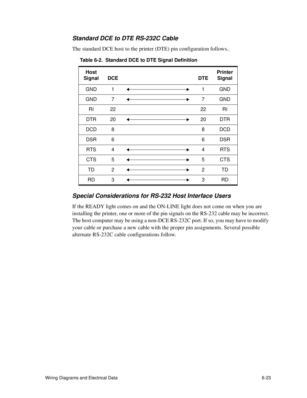
Standard DCE to DTE Signal Definition Host Printer
Standard DCE to DTE RS-232C Cable
Special Considerations for RS-232 Host Interface Users
DTE Host to Printer Option
IBM PC/AT to Printer
IBM PC/XT to Printer
RS-422 Host Interface Connector Wiring Printer
Macintosh Communication Port to Printer
RS-422 Host interface
Centronics Parallel Host Interface
Centronics Parallel Signal Definitions Pin Function Name
IBM Parallel to Printer
10. IBM Parallel to Printer Connector Wiring Host Signal
Mode PRN,,P
Signal Interface Board Settings
Circuit Board Settings
Printhead Circuit Board Settings
PCL Board Settings
Wiring Diagrams and Electrical Data
Removal/Replacement Procedures
Vacuum Transport Unit Removal Simplex
100
Photoconductor Removal
Power Considerations
Removal
Before You Begin
Front Cover Removal
Back Cover Removal
Lower Back Cover Removal
Left Side Cover Removal
Replacement Note
Right Side Cover Removal Simplex
Service kit is attached inside the right side cover
Right Side Cover Removal Duplex
Back Detail
Vacuum Transport Unit Removal Simplex
Vacuum Transport Detail
Spring Detail
Vacuum Transport Unit Removal Duplex
Top Cover Removal
Support Assembly Detail
Support Detail
Top Cover Support Removal
Hinge Detail
Top Cover Hinge Removal
Mounting Screw Detail
Rear Duplex Cover Removal
Gas Spring Detail
Front DuplexCover Removal
Operator Panel Removal
Counter Removal
IGS Board Removal
PCL Board Removal
Printhead Assembly Removal
Front Detail Mounting Screws
Disk Drive Housing Removal
Cooling Fan Detail
Cooling Fan Removal
Duplex Fan Removal
Toner Motor Detail
Toner Motor Removal
AC Power Supply Removal
AC Power Supply Removal
Right Side Detail Back Detail
DC Power Supply Removal
High Voltage Unit Removal
PhotoconductorSeam Sensor Removal
Front Detail
Photoconductor Rear Guide Rail Removal
Spring
Signal Interface Board Removal
Power Control Board Detail
Power Control Board Removal
Jogging Motor Control Board Removal
Jogging Motor Power Control Board Detail
Upper Paper Size Sensor Detail
Upper or LowerPaper Size Sensor Removal
Upper Cassette Mount Removal
Upper Cassette Mount Removal
Upper Cassette Mount Removal
Front Mounting Screw Detail Back Mounting Screw Detail
Cassette Mount Detail Left Side Detail
Lower Cassette Mount Removal
Lower Cassette Mount Removal
Tray Lower Bracket Lower Cassette Mount
Upper Paper Guide Removal
Springs Cassette Release Cover
Upper Paper Guide Roller Removal
Lower Paper Guide Removal
Paper Timing Guide Removal
Paper Feed Drive Cover Mounting Screw CN58
Cleaner Drive Belt Detail
Cleaner Drive Belt Removal
Cleaner Drive Detail
Cleaner Drive Removal
Fuser Drive Belt Removal
Fuser Drive Detail
Fuser Drive Removal
Paper Feed Drive Belt Detail
Paper Feed Drive Belt Removal
Paper Timing Roller Removal
Replacement Notes
Front Detail Cassette Release Cover
Upper Feed Roller Removal
Lower Feed Roller Removal
Upper Pick-Up Roller Removal
Upper Pick-up Roller Drive Detail
Upper Pick-Up Roller Drive Removal
Lower Pick-Up Roller Removal
Lower Pick-up Roller Drive Detail
Lower Pick-Up Roller Drive Removal
Job Offset Assembly Removal
Right Side Detail Back Detail
Exit Pinch Roller Removal
Mounting Screw Fuser Drive Cover
Upper Static Brush Detail
Upper Static Brush Removal
Lower Static Brush Removal
Exit Roller Assembly Removal
Back Detail
Exit Cover Removal Simplex
Mounting Screws Fuser Drive Cover
Exit Cover Removal Duplex
Exit Cover Removal Duplex
Paper Exit Sensor Detail
Paper Exit Sensor Removal
Paper Full Sensor Detail
Paper Full Sensor Removal
Front Cover Interlock Switch Detail
Front Cover Interlock Switch Removal
Back Cover Interlock Switch Detail
Back Cover Interlock Switch Removal
Top Cover Interlock Switch Detail
Top Cover Interlock Switch Removal
Erase Lamp Removal
EP Cover Removal
Replacement Note
Main Motor Removal
Main Motor Detail
Main Gear Drive Detail Fuser Drive Cover
Main Gear Drive Removal
Duplex Control Board #1 Detail
Duplex Control Board #1 Removal
Duplex Control Board #2 Removal
Registration Motor Detail
Duplex Tray Registration Motor Removal
Duplex Skew Correction Cable Removal
Skew Correction Cable Detail
Side Detail
Upper Duplex Drive/Clutch Assembly Removal
Duplex Route Motor/Solenoid Detail
Duplex Route Motor/Solenoid Assembly Removal
Roller Removal
Roller Removal
Upper Duplex Roller Cover Clip and Bearing
Roller Solenoid Detail
Roller Solenoid Removal
Duplex Route Separator Removal
Clip Location
Paper Path Sensor Underside Detail
Duplex Paper Path Sensor Removal
Options
Options
Introduction
Sheet/2500-Sheet Component Acronyms
Sheet/2500-Sheet Feeder
Bench Test Procedure
Bench Test Procedure
Slope Assembly Prefeed Adjustment
Prefeed Adjustment Procedure
Input Control Board Logic
Connection
Diagram for 1200-Sheet/2500-Sheet Feeder
Sheet Stacker Component Acronyms
Sheet Stacker
1400-Sheet Stacker Bench Test Preparation
Options
Connector Locations front view, cover removed
Connector Locations
Rear Side View cover removed
Stacker Actions and Sensor Inputs
Output Control Board Logic
11.Connection Diagram for the 1400-Sheet Stacker
Options
General Printer Maintenance
General Printer Maintenance
General Printer Maintenance Introduction
Tools/Supplies
Tool Requirements Service Kit
End User Cleaning Kit
Printer/Maintenance Record
History LOG
Remove Major Consumable Supplies
Every-Call Cleaning Procedure
Clean Internal Areas
Clean the Fuser Unit
Clean the Transfer Charger
Clean the Developer Unit
Clean the Cleaner Unit/Main Charger
Clean the Photoconductor Unit Area
Printers With Paper Tension Levers
Adjusting Paper Feed Tension
Removing the Cassette Release Cover
Printers With Pick Pressure Adjusters
Paper Pick Pressure Adjusters
Lubrication Procedure
Front View Lubrication Points
Duplex Only
All Printers Front View Lubrication Symbol Part Lubricant
Duplex Front View Lubrication Symbol Part Lubricant
Front View Lubrication Tables
Rear View Lubrication
All Printers Rear View Lubrication Symbol Part Lubricant
Duplex Only Rear Lubrication Symbol Part Lubricant
Rear View Lubrication Tables
Duplex pinch rollers
Drive gears Molycote Tray shaft Red grease
Tune-Up Maintenance Procedure
Tune-Up Kit Components
Introduction
Appendix a Abbreviations and Acronyms
PC . . . . . . . . . . . .Photoconductor
Index
Index-2
Index-3
Index-4
Index-5
Index-6
Index-7