Definity
Comments
Contents
Install Management Terminal Activate System
Install and Wire Telephones Other Equipment
Test Telephones and Other Equipment
Connecting Fiber Optic Cables
About This Book
Organization
How to Comment on This Book
Related Books
How to Order Books
Megacom Systimax Transtalk
Trademarks
CISPR22
Standards Compliance
IEC 825
Laser Product
Electromagnetic Compatibility Standards
European Union Standards
Security Issues
Where to Call for Technical Support
Anti-Static Protection
Telephone Number
Part 68 Statement
Federal Communications Commission Statement
Manufacturer’s Port Identifier FIC Code Network Jacks
Means of Connection
SOC/REN
Unpack and Inspect Cabinets
Install and Connect Cabinets
Check Customer’s Order
Correcting Shipping Errors
Unpack and Inspect Auxiliary Cabinet
Unpack and Inspect Stratum 3 Clock Cabinet
Position the EPN Cabinets
Install System Cabinets
Position the PPN Cabinet
Position the Auxiliary Cabinet Optional
Install Auxiliary Cabinet Equipment
Model 15A Announcement Equipment PEC Code Description
Install and Position Stratum 3 Clock Cabinet
J58890CE-1, J58890CE-2, and J58890CH-1
Connect AC Power and Ground
Power Requirements
Power Distribution Unit Power Sources Power Input
AC Power Sources and Plug Type
AC Load Center is 50 Feet 15.2 m or Less from Cabinet
Connect Ground to AC-Powered System J58890CE
Figure Notes
AC Load Center is More Than 50 Feet 15.2 m from Cabinet
Typical Cabinet Grounding Wiring Diagram
Typical Small Battery Assembly
Connect Battery Leads J58890CH-1
Power Distribution Unit J58890CH
Small Battery Holdover
Connect Shorting Cable to J58890CE-2
Large Battery Holdover
Shorting Cable Installation
Connect AC Power
Rectifier Module Installation
Connect DC Power and Ground
Connect EPN Cabinet Grounds
Connect Power
Connect PPN Cabinet Ground
Typical Power and Ground for a DC-Powered Cabinet
DC Power and Ground J58890CF Only
Connect DC Battery and Power Cabinet Grounds
Connect DC Power and Ground
Install Coupled Bonding Conductor Wires
Connect Main AC Supply to DC Power Cabinet
DC Power Cabinet Approved Ground
Connect Ground Wires for DC-Powered Systems
Turn Circuit Breakers Off
Connect DC Battery Cabinet to DC Power Cabinet
Connect DC Power to PPN and EPN Cabinets
Typical Power and Ground for a Mixed AC/DC-Powered Cabinet
Mixed AC/DC Power and Ground
Approved Grounds
Approved Floor Grounds
Remote Power Off Cable Connections Part
Connect Remote Power Off Cable External Alarm Cable
10. Remote Power Off Cable Connections Part
Check Commercial Power and Connect AC Power
Connect External Alarm Cable
Connect AC Power to Stratum 3 Clock Cabinet
Connect Clock Cabinet Grounding
Connect DC Power and Ground to Stratum 3 Clock Cabinet
Connect Stratum 3 Clock DC Power
Fiber Optic Interconnect Cabling
Connect Fiber Optic Cables
CSS-Connected System with 1 Switch Node Standard-Reliability
High-Reliability
12. High-Reliability CSS-Connected with 1 Switch Node
Critical Reliability
13. Critical-Reliability CSS-Connected with 1 Switch Node
Install Raised Computer Floor Mounting
Earthquake Protection Installation
Install Concrete Floor Mounting
14. Earthquake Mounting Raised Computer Floor
Issue
Equipment Room Hardware
Install Telecommunications Cabling
Example MDF Connections
Cross-Connect Fields
Typical 110A-Type Terminal Blocks
Main Distribution Frame
Sneak Fuse Panels and Emergency Transfer Units
Installation Requirements
Type Hardware
Cable Slack Manager
Hardware Installation
Install Equipment and Cables
Install the Main Distribution Frame
Wall Mounting 110A-Type Terminal Blocks
A-Type Terminal Blocks 300-Pair
P-Type Terminal Blocks 900-Pair
Wall Mounting 110P-Type Terminal Blocks
Frame Mounting 110P-Type Terminal Blocks
Figure Notes
Install Equipment and Cables
Cable Routing Through Cable Slack Manager
Install Cable Slack Managers
Sneak Fuse Panel Ordering Information Description Comcode
Install Sneak Fuse Panels
Model 507B Sneak Fuse Panel
Sneak Fuse Connector Pinout Pair/Fuse Numbers
Labels
Cable Installation
201A Labels Sheets 103969994
Equipment Room Labels Label Name Range
10. Cable Routing to Top Terminal Blocks
Cable Routing Guidelines General
11. Cable Routing to Bottom Terminal Blocks
Route Cables to Main Distribution Frame
Label Control Carrier Cable
Install Control Carrier Outputs Cable
Select Concentrator Cables
Connect Trunk Pairs Using Concentrator Cables
Connect Control Carrier Outputs Cable
12. Connect Trunk Pairs Using Concentrator Cables
13 -Pair Modularity for Trunk Pairs for 1-Pair Trunks
14 -Pair Modularity for Trunk Pairs for 3-Pair Tie Trunks
Install Cables Between Cabinet and MDF
Install Connector Cables Between Auxiliary Cabinet and MDF
Install Coupled Bonding Conductor
15. Coupled Bonding Conductor
Station Cables
Station Wiring Design
Information Outlets
Gray 103942272 Ivory 103786240
451A Adapter Ordering Information Color Comcode
16. Example of Extending 4-Pair Station Cables
Closets Site Locations
17 a and BR2580A Adapters
Adapter Ordering Information Description Comcode
18 a Adapter
Satellite Locations
Satellite Locations Using 110-Type Hardware
Station Circuit Distribution from Equipment Room
19 -Pair Circuit Distribution and Connectivity
Pair Station Circuits
20 -Pair Run to Equipment Room or Satellite Location
21 -Pair Run to Equipment Room or Satellite Location
22 -Pair to 4-Pair Satellite Location Connectivity
Pair to 4-Pair Station Circuit Distribution
23 -Pair to 4-Pair Circuit Distribution and Connectivity
Layout
Voice and Data Terminals Station Type
Voice and Data Terminals
Pair Station Cable Circuits
Issue
ISDN-BRI
Type
Label the Main Distribution Frame
Administration Terminals
Administration Terminals Application
24. Label Graphic Symbols and Nomenclature
Patch Cord/Jumper Installation Administration
25. Port Assignment Record Form
Labeling
26. Example 3-Pair Labeling to Information Outlet
27. Example 4-Pair Labeling to Information Outlet
Create a Provisioning Plan
Issue
Install Management Terminal Activate System
Typical Management Terminal
Install Management Terminal
Install a 2900/715 BCS Terminal
Install a 715 BCS Terminal
Install a 715 BCS-2 Terminal
Unpack and Inspect
Rear Panels on Management Terminals
Connect to the System
Management Terminal Connections for Release 6si
Typical Connections to Remote Devices
Remotely Connect Terminal
Install Management Applications
Set Up Management Terminal
Install Translation Card Release 6si in MCC Cabinet
Power Up the System AC-Powered System
Verify Messages on Terminal
DC-Powered System
Screen 3-1. Typical Start-up Messages Release 6r
Login
Commands
Screens and Commands
Screens
Getting Help
Log in to the System
System Administration
Screen 3-2. Typical System Parameters Country-Options Screen
Set Country Options
USA
Country Codes
Screen 3-3. Typical Change Password Screen
Change Craft Password
English Day of the Week Names Day Number Day Name
Set Date and Time
Screen 3-4. Typical Date and Time Screen
English Month Names Month Number
Circuit Pack Administration
Screen 3-5. Typical System-Parameters Maintenance Screen
Set System Maintenance Parameters
Change Customer Options
Administer System Configurations Release 6r
Screen 3-6. Typical Customer-Options Form
Change and Logoff Critical Reliability System
Screen 3-7. Typical Change Cabinet 1 Form
Change Site-Data
Change Cabinet
Screen 3-8. Typical Add Cabinet Form
Add Cabinet 2 through N Release 6r
Enter add cabinet 2-44. See Screen
Circuit Pack Form
Administer Fiber Links Release 6r Only
Screen 3-9. Circuit Packs Form
Administer Fiber Links on Simplex Systems
E1 Installations Only
T1 Installations Only
Administer Fiber Links on Duplex Systems
All Installations
Issue
T1 Installations Only
Administer Attendant Console
Reboot High Reliability System
Enter reset system
Enter change system-parameters duplication
Add Translations
Save Translations
Save Translations Release 6si
Save Translations Release 6r
Logoff the System
Installation Completion
Power Up the Audix System
Definity Audix Power Procedures
Power Down the Audix System
Test the System
Screen 4-1. Example System Status Screen for Cabinet
Check System Status for Each Cabinet
Screen 4-2. Example System Configuration Screen
Check Circuit Pack Configuration
Type list configuration all and press Enter
Screen 4-3. Example Test Results for TDM Port Network
Test TDM Bus in PPN
Type test tdm port-network 1 and press Enter
Screen 4-4. Example Test Results for Tone-Clock 1A
Test Tone-Clock Circuit Packs
Type test tone-clock 1a and press Enter
Type test shadow-link and press Enter
Test SPE Duplication Memory Shadowing Link
Screen 4-6. Example System Status Report for All Cabinets
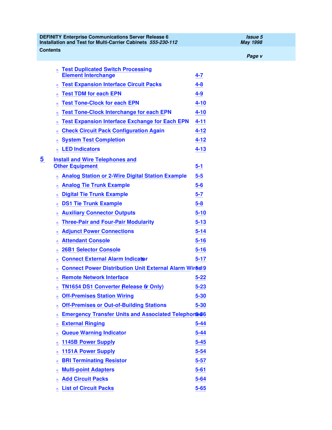
Test Duplicated Switch Processing Element Interchange
Screen 4-7. Example Test Board 1C03
Test Expansion Interface Circuit Packs
Screen 4-8. Example Test Results for TDM Port Network
Test TDM for each EPN
Type test tdm port-network 2 and press Enter
Type status system all-cabinets and press Enter
Test Tone-Clock for each EPN
Test Tone-Clock Interchange for each
Enter status cabinet 1-44 and press Enter. See Screen
Test Expansion Interface Exchange for Each EPN
System Test Completion
Check Circuit Pack Configuration Again
Save Translations
Next Steps
Attendant Console LEDs
LED Indicators
Terminal Alarm Notification
Color Status Description
Circuit Pack LEDs
Circuit Pack LEDs
Span LEDs
DS1 Converter Circuit Pack LEDs
TN1654 DS1 Converter Circuit Pack LEDs
LEDs on Standby Components
Install and Wire Telephones Other Equipment
Punch-downs for Common Circuit Packs
Telephone Connection Example
C to TN754B Wiring
B2 Adapter Connecting to a Modular Plug
Connect Adjunct Power
Type Analog Telephone Wiring
Analog Station or 2-Wire Digital Station Example
Analog Tie Trunk Example
Analog Tie Trunk Wiring
Digital Tie Trunk Example
Digital Tie Trunk Wiring
Collocated DS1 Tie Trunks
Pinout of C6F Cable Wire Color Lead Designation Pin Number
DS1 Tie Trunk Example
Typical Connections to Channel Service Unit
DS1 Tie Trunks Using Channel Service Unit
Auxiliary Connector Outputs
Auxiliary Lead Appearances at AUX Connector
GRD
Port Circuit Pack and Telephone Pin Designations
Pair and 4-Pair Modularity
Three-Pair and Four-Pair Modularity
Example Adjunct Power Connections
Adjunct Power Connections
Auxiliary Power
Local and Phantom Power
AWG Wire 0.26 mm AWG Wire 0.14 mm
Attendant Console Cabling Distances Enhanced Attendant
Dual Wiring of Two-Wire and Four-Wire Endpoints
Hard-Wire Bridging
Attendant Console
26B1 Selector Console
Alarm Input
Connect External Alarm Indicators
Alarm Output
Alarm Inputs at AUX Connector Color
Emergency Transfer and Auxiliary Power Color AUX Connector
Emergency Transfer and Auxiliary Power
External Alarm Connector Pinout Designation Definition
Connect Power Distribution Unit External Alarm Wires
DTR
Issue
10. Connections at Trunk/Auxiliary Field
Remote Network Interface
TN1654 DS1 Converter Release 6r Only
Set Circuit Pack Switches
TN1654 DS1 Converter Configuration Switches Function Down
11. DS1 Converter Circuit Pack Switches
12. DS1 Converter Connections Part
Install the Circuit Pack and Cabling T1 Only
Port Carrier
Switch Node Carrier
Port Carrier to Switch Node Carrier
13. DS1 Converter Connections Part
Channel Service Unit Cabling
10. Y Cable Lengths Description Comcode
Install the Circuit Pack and Cabling E1 Only
14. DS1 Converter Connections E1 Only
E1 Interface Cabling
Analog Off-Premises Stations
Off-Premises Station Wiring
Off-Premises or Out-of-Building Stations
Off-Premises or Out-of-Building Stations
16. Connections to 24 Out-of-Building Telephones
Primary Sneak Current With heat coil Protectors
11. Analog Line Circuit Protectors
Protectors
Protector Ordering Information Description Comcode
Digital Out-of-Building Voice Terminals
Issue
Emergency Transfer Units Associated Telephones
17 a Emergency Transfer Panel
808A Emergency Transfer Panel
Switch Circuit Number
Trunk/Test Switches
Pin Color Designation Connector/Description
14. Pin Assignments for 25-Pair Connector
TST4
18. Connections for Telephone Used for Emergency Transfer
R758582b MMR
Telephone Installation
External Ringing
Queue Warning Indicator
1145B Power Supply
Wall-Mounting Plates
20 B/1146B Mounting Arrangement
15. Back-Up Battery PEC Codes Rating
Mount the 1146B Power Distribution Unit
Battery Mounting/Wiring
Install the Expanded Power Distribution Unit
21. Expanded Power Distribution Unit
Power Up and Test
Reset LEDs on Power Distribution Unit
Wire the 1146B Power Distribution Unit
Issue
Important Safety Instructions
1151A Power Supply
Do not locate the unit within 6 inches 15.2 cm of the floor
1151Aand 1151A2 Power Supplies
22. Typical 1151A Power Supply Front
Connect the 1151A or 1151A2 Power Supplies
BRI Terminating Resistor
23 -Wide Terminating Resistor Adapter 440A4
Terminating Resistor Adapter
24. Terminating Resistor Block 110RA1-12
Closet Mounted 110RA1-12
T1 R1
BR851-B Adapter T-Adapter
Multi-point Adapters
367A Adapter
Wiring Diagram of 367A
28. Basic Multi-point with 1 Work Location
Basic Multipoint Installation Distances
Add Circuit Packs
CPP1
List of Circuit Packs
On next
Multimedia Interface Service
On next
On next
Add the Fiber Optic Cable
29. Fiber Pass-Thru Kit Equipment
Quantity Description Comcode
Laser Product
Cabinet Preparation
Issue
30. Remove the I/O Cable Connector
31. Secure the I/O Cable Connector
32. Remove the Fan Cover
Install the Pass-thru Kit
33. Fiber Optic Adapter and Pass-Thru Tool
34. Insert the Pass-thru Tool
35. Fiber Optic Cable and Adapter
36. Bracket Attachments
37. Cable Disconnect Label
38. Replace the Fan Cover
39. Connect Fiber Cable to Circuit Pack
40. Dress the Cable
Test the Installation
Requirements
Installation
Add CO, FX, WATS, and Pcol
Add did Trunks
Add Tie Trunks
Smplx
Add DS1 Tie and OPS
Service Interruption
Disable Alarm Origination
Shut Down Definity Audix System
Shut Down Definity LAN Gateway System
Install Cables
Power Down System
Power Up System
Add Circuit Packs
Resolve Alarms
Enable Customer Options
Add Pooled Modem
Add Code Calling Access
Add Speech Synthesis
Robotics Model 839 External Modem
Add External Modem to EPN
43. Connect External Modem to PPN
Add External Modem to PPN
44. Pass-Thru Kit Equipment
Add External Modem to TN1648B
Cabinet Preparation
45. Remove the Fan Cover
46. Insert the Cable Assembly through the Rear Panel
47. Attach the Panel Adapter Bracket
Insert the cable assembly as shown in Figure
49. Attach the Cable to the Pass-Thru Tool
50. Insert the Pass-thru Tool
51. Replace the Fan Cover
52. Connect the Cable to the Circuit Pack
TN750C Announcement Circuit Pack
Save and Restore Recorded Announcements
Add Multiple Announcement
TN750 and TN750B Announcement Circuit Packs
Issue
Add Additional TN750C Circuit Packs
Add Isdn PRI
Enter change system-parameters maintenance and press Enter
North American
European
Save Translations
Enter Added Translations
Add Packet Bus to R6si
Standard Reliability R6si System Disable Alarm Origination
Install Circuit Packs
Perform tests
Power Down the Control Carrier
Power up the system
Add CallVisor Asai
Port Number
Install cables from cabinet to the MDF as required
Save Translations
Add ISDN-BRI
Cabinet Carrier Slot Circuit Port Network
Resolve Alarms
Tone-Clock Circuit Packs
Add PRI Over Paccon to R6si
Expansion Interface EI Circuit Packs
DS1/E1 Interface Circuit Packs
Service Interruption
Install cables from the cabinet to the MDF as required
Assign ISDN-PRI and PRI Over Paccon Options
Assign or Reassign ISDN-PRI Feature
Remove signaling-group nn For each signaling group assigned
Behind the PPN, set the circuit breaker to on
Reboot the System
Enable Customer Options
Logoff and log back in as craft
Configuration
CAMA/E911 Installation
On next
On next
Administration Setup
Hardware Setup
Screen 5-1. Cama Trunk Group form
Screen 5-2. Administrable Timers form
Screen 5-3. Group Member Assignments form
Feature Access Code FAC
Screen 5-4. Feature Access Code FAC form
ARS Digit Analysis Table
Screen 5-5. ARS Digit Analysis Table
Enter
Screen 5-6. Route Pattern form
Screen 5-7. Route Pattern form
Screen 5-8. Cama Numbering Format form
Type Save Translation and press Enter
Screen 5-9. Class of Restriction form
Cross- Connect Pin Color Amphenol Pin Backplane Pin
Connector and Cable Diagrams Pinout Charts
25. Lead and Color Designations
Connector and Cable Diagrams Pinout Charts
TXT.1
BR-W
28. Port Circuit Pack Lead Designations
LOOP2 SL-W LOOP1
Plug
31. TN1654 Lead Designations
32. TN793 24-Port Analog Line Lead Designations
33. Circuit Pack and Auxiliary Equipment Classifications
Issue 5 May
34. Circuit Pack and Auxiliary Equipment Leads Pinout Charts
Wire Data Digital Line Connector Analog
LI, LI
Issue
Test Telephones and Other Equipment
Test Selector Console
Make Test Calls
Test 302C Attendant Console
Test Integrated Announcement
Test Queue Warning Indicator
Test External Ringing
Test Music-on-Hold
Test Remote Access Interface
Test Emergency Transfer
Remote Test
Test Basic Rate Interface
Enter refresh-spr-standby command
Test Duplication Option Processing Element Interchange
Local Test
Test Terminating Trunk Transmission
Check for Red LEDs
Stratum 3 Clock LED Indicators Card LED Label Procedure
Test Stratum 3 Clock
Verify Timing to the System
Perform Complete System Test
Activate and Test Alarm Origination Feature
Activate and Test Alarm Origination Feature
Connecting Fiber Optic Cables
Fiber Optic Requirements
Single-Mode Fiber Optic Connections
Fiber Optic Cable Connections
Multi-Mode Fiber Optic Connections
Fiber Optic Component Comcodes
A-5
Optical Cross-Connect Hardware
Measuring Single-Mode Power in the Field
Figure A-1. Single-Mode Attenuator Requirements
When to Use Single-Mode Fiber Attenuators
Figure A-2. Typical Single-Mode Connection with Attenuator
Single-Mode Fiber Link with Attenuators
Lightguide Distribution Shelf
Lightguide Troughs
100A and 200A Lightguide Equipment
Lightguide Interconnect Units
Figure A-4 a Lightguide Interconnection Unit
10A and 1000ST Lightguide Coupling Panel
Figure A-5 a and 1000ST Lightguide Connector Coupling
Figure A-6 a LIU Equipment
400A Lightguide Equipment
General Rules and Recommendations
Rule
Labels for Fiber Optic Cables
Cleaning Fiber Optic Cables
Cable Labels
Cross-Connect Labels
To Make a New Cross-Connection
Making Changes at an LIU or Shelf
To Remove a Fiber Optic Patch Cord
To Make a New Interconnection
Routing Fiber Optic Cables
Cable Slack Managers or Raised Floors
Overhead Ductwork
Option Switch Settings
Table B-1. Modem Fields Connection Description
External Modem Option Settings
External Modem Option Settings B-3
External Modem Option Settings B-4
Figure B-1. Control Panel for 572 Printer
Printer Option Settings
Function Function Name Menu Menu Status
Table B-2 Printer Used with Management Terminal
Table B-3 Printer used as System Printer
Call Detail Recording Option Settings
Data BIT Protocol XON/XOFF Stop BIT Parity None PBS
Table B-5. Signaling Formats for TN760D Mode Type
TN760D Tie Trunk Option Settings
B-11
Table B-8. Option Switch Settings on TN464E/F
TN464E/F Option Settings
Cable Ductwork
Figure C-1. Typical Layout of Assembled Ductwork
Table C-1. ED-1E465 Group Numbers and Descriptions
C-4
Table C-2. Installation Sequence Step Group Remarks
Figure C-2. Overhead View of a Typical Ductwork Layout
Figure C-3. Dust Cover Removal
Install Intercabinet Shielded Ducts
Figure C-4. Assembly of Intercabinet Shielded Ducts
Install Cross-Aisle Shielded Ducts
Figure C-5. Assembly of Cross-Aisle Shielded Ducts
Assemble cross-aisle ductwork as already described
Mating Cross-Aisle Risers to Old Cabinet Risers
Mating Shielded Ducts to Risers
Install Cross Aisle I/O Ductwork
C-13
Figure C-9. Installation of I/O Cross-Aisle to Wall Trough
Install Cross-Aisle to Wall Trough
Install I/O Cable Rack Coupling
Install I/O Cable Rack Riser
Install AC Power Duct
Figure C-12. Install AC Power Duct
Figure C-13. Assembly of Ladder Rack
C-20
Connector and Cable Diagrams
D-2
D-3
Figure D-3. Sample Cross-Connects
Figure D-4. Sample Cable Pinouts
Figure D-5. Sample Pinouts
Figure D-6. Sample Cable Pinouts
Figure D-7. Stratum 3 Clock Connector Pinout
Figure D-8. Stratum 3 Clock Connector
Figure D-9. Sample H600-274 Cable
Basic Definity ECS Documents
Administration
555-230-303
555-230-211
555-230-511
Installation and Maintenance
555-230-120
555-230-121
CentreVu CMS
Issue 1
Call Center Documents
555-230-222
Application-Specific Documents
555-230-221
555-230-220
555-230-114
Definity ECS Release 6 Call Visor Asai Overview, Issue 2
Console Operations
Call Detail Recording
Hospitality
555-230-890
555-230-833
Documents on CD-ROM
Documents on CD-ROM
Numerics
ADC
Accunet
Adap
ADU
ADM
AIM
Aiod
Ansi
ANI
AOL
Aplt
Asai
ARS
ATB
ATD
Audix
ATM
AVD
AUX
Awoh
AWG
Bhcc
BER
BLF
BOS
CAG
BTU
Cacr
CAS
Cama
CARR-POW
CBC
CA-TSC
Ccis
Ccitt
Cispr
CEM
CEPT1
COS
COR
CPN
CPE
CPN/BN
Cptr
DAC
DCP
DCO
DCS
DDC
Digital signal level 1 DS1
Digital signal level 0 DS0
Digital data endpoints
Digital multiplexed interface DMI
Diva
Diod
DLC
Dldm
DOT
Doss
DPM
DPR
DXS
Dwbs
EAL
Ebcdic
EPN
EMI
Eprom
Epscs
Etsi
ETN
FAS
FAC
FAT
FAX
G3-MA
FRL
G3-MT
Gptr
Hnpa
ICC
IAS
ICD
Icdos
INS
Isdn
Inwats
IS/DTT
ISN
LAN
IXC
LAP-D
Lapd
LSU
Linl
LWC
MAC
MAP
Madu
Mapd
MA-UUI
MFB
MET
MFC
MIM
MS/T
MOS
Mpdm
MWL
NAU
Nanp
NCA/TSC
Ncoss
NPE
NPA
NQC
NSE
ONS
OCM
OPS
OPX
PBX
PAD
PCM
Pcol
Pktint
Pidb
PLS
PMS
PPN
PPM
PRI
Procr
Psdn
PSC
PTC
PTT
RCL
RBS
REN
RFP
Rose
RSC
Sabm
SAC
SCD
SCC
SCI
SCO
SSM
SSI
SSV
ST3
Sysam
SVN
SXS
Tabs
Taas
TAC
TCM
TOP
TOD
TTI
TSC
TTR
TTT
VDN
VAR
VIS
Vlsi
WSS
WSA
ZCS
Index
Audix
BRI
Pin designations, 5-143,5-153 to 5-155,D-1
DC, 1-19 signaling leads, B-10
DS1
Cables, 1-29 to
Inads
IN-9
IN-10
IN-11
IN-12
IN-13
IN-14