Parameter Description | Issue 01/06 |
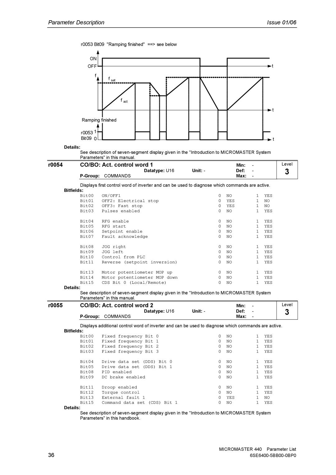
r0053 Bit09 "Ramping finished" ==> see below
ON
OFF
f
f set
fact
Ramping finished
r0053 1 Bit09 0
![]() t
t
![]() t
t
![]() t
t
Details:
See description of
r0054 | CO/BO: Act. control word 1 |
| Min: | - |
| Datatype: U16 | Unit: - | Def: | - |
|
| Max: | - |
Displays first control word of inverter and can be used to diagnose which commands are active.
Bitfields: |
|
|
|
|
|
Bit00 | ON/OFF1 | 0 | NO | 1 | YES |
Bit01 | OFF2: Electrical stop | 0 | YES | 1 | NO |
Bit02 | OFF3: Fast stop | 0 | YES | 1 | NO |
Bit03 | Pulses enabled | 0 | NO | 1 | YES |
Bit04 | RFG enable | 0 | NO | 1 | YES |
Bit05 | RFG start | 0 | NO | 1 | YES |
Bit06 | Setpoint enable | 0 | NO | 1 | YES |
Bit07 | Fault acknowledge | 0 | NO | 1 | YES |
Bit08 | JOG right | 0 | NO | 1 | YES |
Bit09 | JOG left | 0 | NO | 1 | YES |
Bit10 | Control from PLC | 0 | NO | 1 | YES |
Bit11 | Reverse (setpoint inversion) | 0 | NO | 1 | YES |
Bit13 | Motor potentiometer MOP up | 0 | NO | 1 | YES |
Bit14 | Motor potentiometer MOP down | 0 | NO | 1 | YES |
Bit15 | CDS Bit 0 (Local/Remote) | 0 | NO | 1 | YES |
Details:
See description of
Level
3
r0055 | CO/BO: Act. control word 2 |
| Min: | - |
| Datatype: U16 | Unit: - | Def: | - |
|
| Max: | - |
Level
3
Displays additional control word of inverter and can be used to diagnose which commands are active.
Bitfields: |
|
|
|
|
|
Bit00 | Fixed frequency Bit 0 | 0 | NO | 1 | YES |
Bit01 | Fixed frequency Bit 1 | 0 | NO | 1 | YES |
Bit02 | Fixed frequency Bit 2 | 0 | NO | 1 | YES |
Bit03 | Fixed frequency Bit 3 | 0 | NO | 1 | YES |
Bit04 | Drive data set (DDS) Bit 0 | 0 | NO | 1 | YES |
Bit05 | Drive data set (DDS) Bit 1 | 0 | NO | 1 | YES |
Bit08 | PID enabled | 0 | NO | 1 | YES |
Bit09 | DC brake enabled | 0 | NO | 1 | YES |
Bit11 | Droop enabled | 0 | NO | 1 | YES |
Bit12 | Torque control | 0 | NO | 1 | YES |
Bit13 | External fault 1 | 0 | YES | 1 | NO |
Bit15 | Command data set (CDS) Bit 1 | 0 | NO | 1 | YES |
Details:
See description of
36 | MICROMASTER 440 Parameter List |