Issue 01/06 | Parameter Description |
P1113[3] BI: Reverse |
|
| Min: | 0:0 | |
CStat: | CT | Datatype: U32 | Unit: - | Def: | 722:1 |
COMMANDS | Active: first confirm | QuickComm.: No | Max: | 4000:0 | |
Defines source of reverse command.
Index:
P1113[0] : 1st. Command data set (CDS)
P1113[1] : 2nd. Command data set (CDS)
P1113[2] : 3rd. Command data set (CDS)
Common Settings:
722.0= Digital input 1 (requires P0701 to be set to 99, BICO)
722.1= Digital input 2 (requires P0702 to be set to 99, BICO)
722.2= Digital input 3 (requires P0703 to be set to 99, BICO)
722.3= Digital input 4 (requires P0704 to be set to 99, BICO)
722.4= Digital input 5 (requires P0705 to be set to 99, BICO)
722.5= Digital input 6 (requires P0706 to be set to 99, BICO)
19.B = Reverse via BOP
Dependency:
Active only when P0719 < 10. See parameter P0719 (Selection of command/setpoint source).
Level
3
r1114 | CO: Freq. setp. after dir. ctrl. |
| Min: | - |
| Datatype: Float | Unit: Hz | Def: | - |
|
| Max: | - |
Displays setpoint frequency after change of direction.
Level
3
r1119 | CO: Freq. setpoint before RFG |
| Min: | - |
| Datatype: Float | Unit: Hz | Def: | - |
|
| Max: | - |
Displays output frequency after modification by other functions, e.g.:
-P1110 BI: Inhibit neg. freq. setpoint,
-P1091 - P1094 skip frequencies,
-P1080 Min. frequency,
-P1082 Max. frequency,
-limitations,
-etc.
Level
3
3.21Ramp-function generator
P1120[3] |
|
|
| Min: | 0.00 | |
| CStat: | CUT | Datatype: Float | Unit: s | Def: | 10.00 |
| SETPOINT | Active: first confirm | QuickComm.: Yes | Max: | 650.00 | |
Level
1
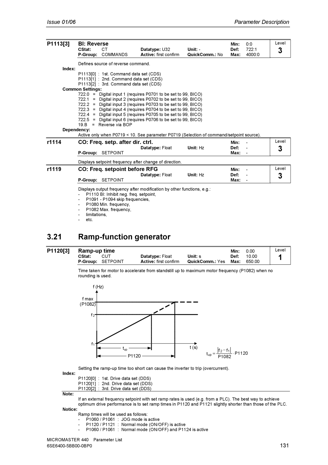
Time taken for motor to accelerate from standstill up to maximum motor frequency (P1082) when no rounding is used.
f (Hz)
f max |
|
|
(P1082) |
|
|
f 2 |
|
|
f1 |
| t (s) |
tup |
| |
| P1120 | tup = |
|
|
| f 2 | − f1 |
| ⋅ P1120 |
| P1082 | |||
|
| |||
Setting the
Index:
P1120[0] : 1st. Drive data set (DDS)
P1120[1] : 2nd. Drive data set (DDS)
P1120[2] : 3rd. Drive data set (DDS)
Note:
If an external frequency setpoint with set ramp rates is used (e.g. from a PLC). The best way to achieve optimum drive performance is to set ramp times in P1120 and P1121 slightly shorter than those of the PLC.
Notice:
Ramp times will be used as follows:
-P1060 / P1061 : JOG mode is active
-P1120 / P1121 : Normal mode (ON/OFF) is active
-P1060 / P1061 : Normal mode (ON/OFF) and P1124 is active
MICROMASTER 440 | Parameter List |
131 |