Parameter Description | Issue 01/06 |
r1482 | CO: Integral output of |
| Min: | - |
| Datatype: Float | Unit: Nm | Def: | - |
|
| Max: | - |
Displays integral part of speed controller output.
Level
3
3.29.2.2Droop
P1488[3] Droop input source |
|
| Min: | 0 | |
CStat: | CUT | Datatype: U16 | Unit: - | Def: | 0 |
CONTROL | Active: first confirm | QuickComm.: No | Max: | 3 | |
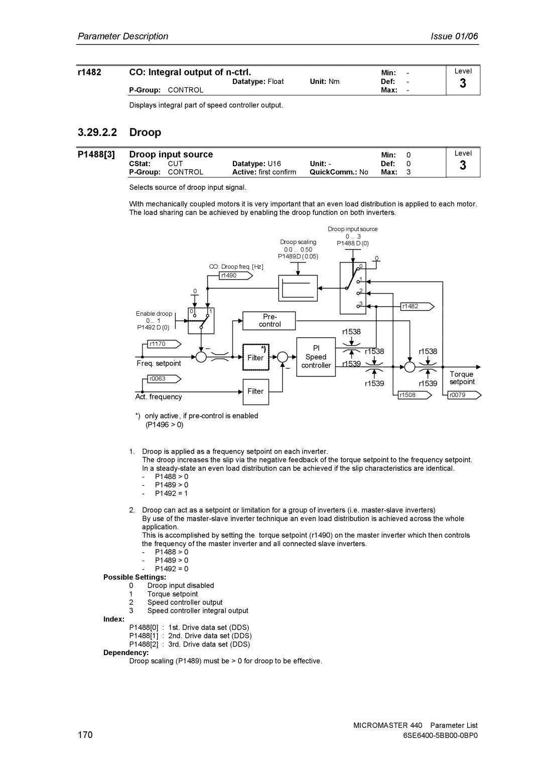
Selects source of droop input signal.
Level
3
With mechanically coupled motors it is very important that an even load distribution is applied to each motor. The load sharing can be achieved by enabling the droop function on both inverters.
0
Enable droop | 0 |
| |
0 ... 1 |
|
P1492.D (0) |
|
r1170 |
|
Freq. setpoint
r0063
Act. frequency
| Droop input source |
Droop scaling | 0 ... 3 |
P1488.D (0) |
|
| 0.0 ... 0.50 |
|
|
|
| |
|
| P1489.D (0.05) |
| 0 |
|
| |
|
|
|
|
|
|
| |
CO: Droop freq. [Hz] |
|
| 0 |
|
|
| |
| r1490 |
|
| 1 |
|
|
|
|
|
|
|
|
|
| |
|
|
|
| 2 |
|
|
|
|
|
|
| 3 | r1482 |
|
|
1 |
|
|
|
|
|
| |
Pre- |
|
|
|
|
|
| |
|
|
|
|
|
|
| |
| control |
| r1538 |
|
|
| |
|
|
|
|
|
|
| |
– | *) |
| PI |
| r1538 | r1538 |
|
| Filter |
| Speed | r1539 |
|
|
|
|
| – | controller |
|
| Torque | |
|
|
|
|
|
| ||
|
|
|
|
|
|
| |
| Filter |
|
|
| r1539 | r1539 | setpoint |
|
|
|
| r1508 |
| r0079 | |
|
|
|
|
|
| ||
*) only active, if
1.Droop is applied as a frequency setpoint on each inverter.
The droop increases the slip via the negative feedback of the torque setpoint to the frequency setpoint. In a
-P1488 > 0
-P1489 > 0
-P1492 = 1
2.Droop can act as a setpoint or limitation for a group of inverters (i.e.
By use of the
This is accomplished by setting the torque setpoint (r1490) on the master inverter which then controls the frequency of the master inverter and all connected slave inverters.
-P1488 > 0
-P1489 > 0
-P1492 = 0
Possible Settings:
0Droop input disabled
1Torque setpoint
2Speed controller output
3Speed controller integral output
Index:
P1488[0] : 1st. Drive data set (DDS)
P1488[1] : 2nd. Drive data set (DDS)
P1488[2] : 3rd. Drive data set (DDS)
Dependency:
Droop scaling (P1489) must be > 0 for droop to be effective.
170 | MICROMASTER 440 Parameter List |