Parameter Description | Issue 01/06 |
t
VDC | VDC, act |
VDC, Chopper
t
Chopper ![]() active
active
t
tChopper , ON
|
|
|
| t |
t Chopper | = | 1 | = | 1 |
|
| f Chopper |
| 2000Hz |
VDC, act
–
VDC, Chopper
100 % |
| 0 |
|
| |
∆ V | V | 1 |
| ||
|
|
1![]()
0
| P1237 |
Duty cycle | 1 |
| |
monitoring | 0 |
x | tChopper , ON = | x | ⋅ t Chopper | |
100 | ||||
|
|
|
Alarm
A0535
|
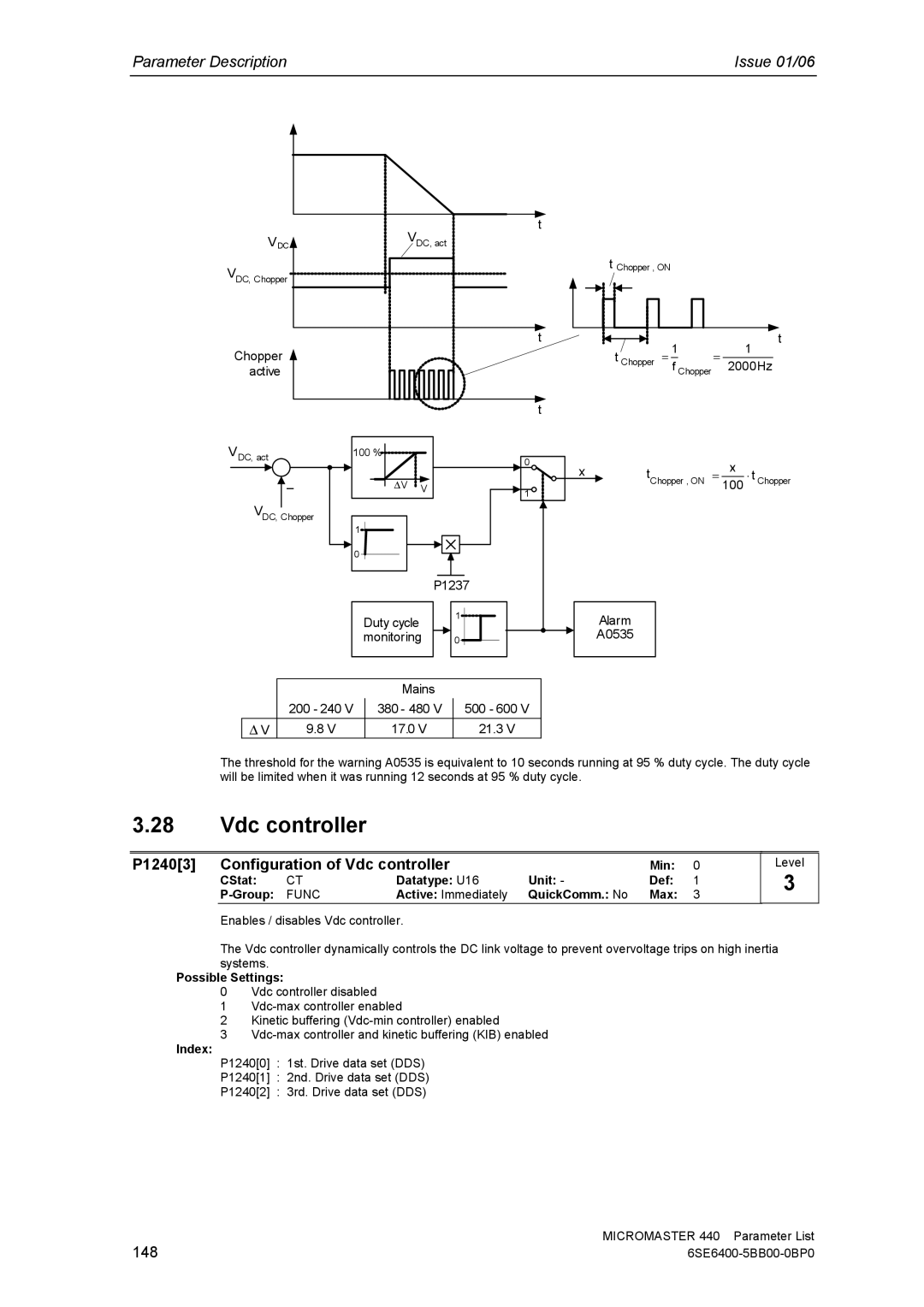
| Mains |
|
| 200 - 240 V | 380 - 480 V | 500 - 600 V |
∆ V | 9.8 V | 17.0 V | 21.3 V |
The threshold for the warning A0535 is equivalent to 10 seconds running at 95 % duty cycle. The duty cycle will be limited when it was running 12 seconds at 95 % duty cycle.
3.28Vdc controller
P1240[3] | Configuration of Vdc controller |
| Min: | 0 | ||
| CStat: | CT | Datatype: U16 | Unit: - | Def: | 1 |
| FUNC | Active: Immediately | QuickComm.: No | Max: | 3 | |
Enables / disables Vdc controller.
Level
3
The Vdc controller dynamically controls the DC link voltage to prevent overvoltage trips on high inertia systems.
Possible Settings:
0Vdc controller disabled
1
2Kinetic buffering
3
Index:
P1240[0] : 1st. Drive data set (DDS)
P1240[1] : 2nd. Drive data set (DDS)
P1240[2] : 3rd. Drive data set (DDS)
148 | MICROMASTER 440 Parameter List |