Parameter Description | Issue 01/06 |
Notice:
When choosing the setting for measurement, observe the following:
1."with parameter change"
means that the values are actually adopted as Pxxxx parameter settings (see common settings above) and applied to the controller as well as being shown in the
2."without parameter change"
means that the values are only displayed, i.e. shown for checking purposes in the
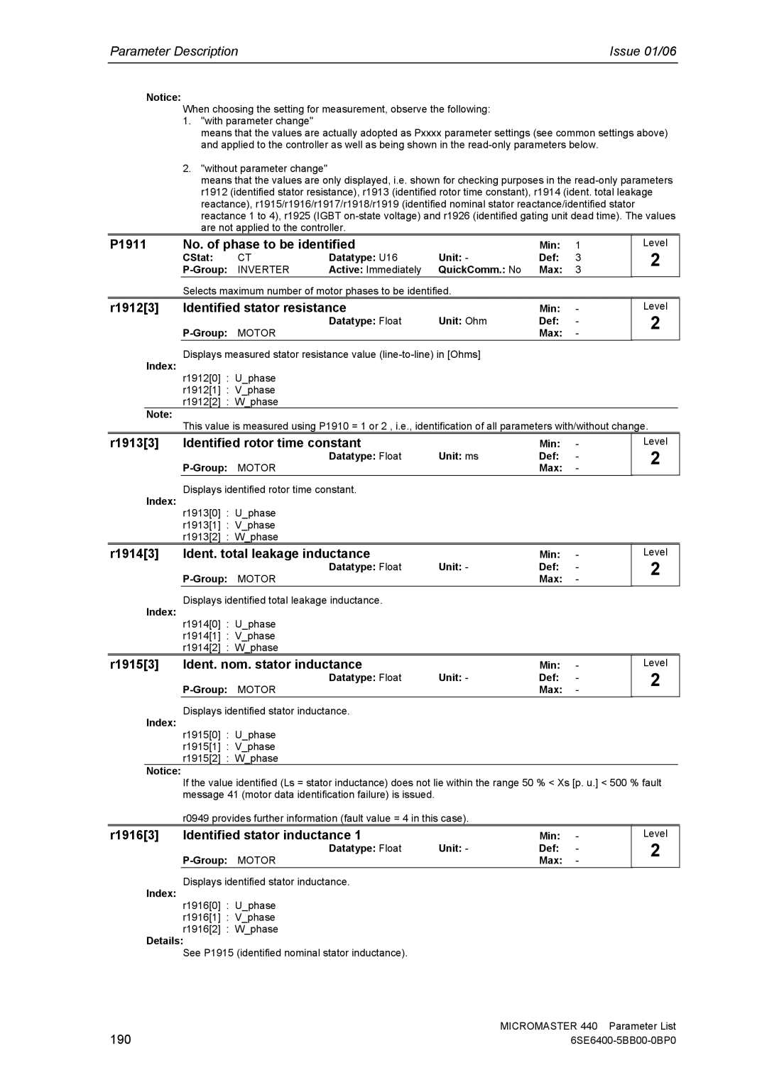
P1911 | No. of phase to be identified |
| Min: | 1 | ||
| CStat: | CT | Datatype: U16 | Unit: - | Def: | 3 |
| INVERTER | Active: Immediately | QuickComm.: No | Max: | 3 | |
Selects maximum number of motor phases to be identified.
Level
2
r1912[3] | Identified stator resistance |
| Min: | - |
| Datatype: Float | Unit: Ohm | Def: | - |
|
| Max: | - |
Level
2
Displays measured stator resistance value
Index:
r1912[0] : U_phase
r1912[1] : V_phase
r1912[2] : W_phase
Note:
This value is measured using P1910 = 1 or 2 , i.e., identification of all parameters with/without change.
r1913[3] | Identified rotor time constant |
| Min: | - | Level |
| Datatype: Float | Unit: ms | Def: | - | 2 |
|
| ||||
|
| Max: | - |
| |
Index: | Displays identified rotor time constant. |
|
|
|
|
r1913[0] : U_phase |
|
|
|
| |
|
|
|
|
| |
| r1913[1] : V_phase |
|
|
|
|
| r1913[2] : W_phase |
|
|
|
|
r1914[3] | Ident. total leakage inductance |
| Min: | - | Level |
| Datatype: Float | Unit: - | Def: | - | 2 |
|
| Max: | - |
| |
Index: | Displays identified total leakage inductance. |
|
|
|
|
r1914[0] : U_phase |
|
|
|
| |
|
|
|
|
| |
| r1914[1] : V_phase |
|
|
|
|
| r1914[2] : W_phase |
|
|
|
|
r1915[3] | Ident. nom. stator inductance |
| Min: | - | Level |
| Datatype: Float | Unit: - | Def: | - | 2 |
|
| ||||
|
| Max: | - |
| |
Index: | Displays identified stator inductance. |
|
|
|
|
r1915[0] : U_phase |
|
|
|
| |
|
|
|
|
| |
| r1915[1] : V_phase |
|
|
|
|
| r1915[2] : W_phase |
|
|
|
|
Notice:
If the value identified (Ls = stator inductance) does not lie within the range 50 % < Xs [p. u.] < 500 % fault message 41 (motor data identification failure) is issued.
r0949 provides further information (fault value = 4 in this case).
r1916[3] | Identified stator inductance 1 |
| Min: | - |
| Datatype: Float | Unit: - | Def: | - |
|
| Max: | - |
Displays identified stator inductance.
Index:
r1916[0] : U_phase
r1916[1] : V_phase
r1916[2] : W_phase
Details:
See P1915 (identified nominal stator inductance).
Level
2
190 | MICROMASTER 440 Parameter List |