Issue 01/06 | Parameter Description |
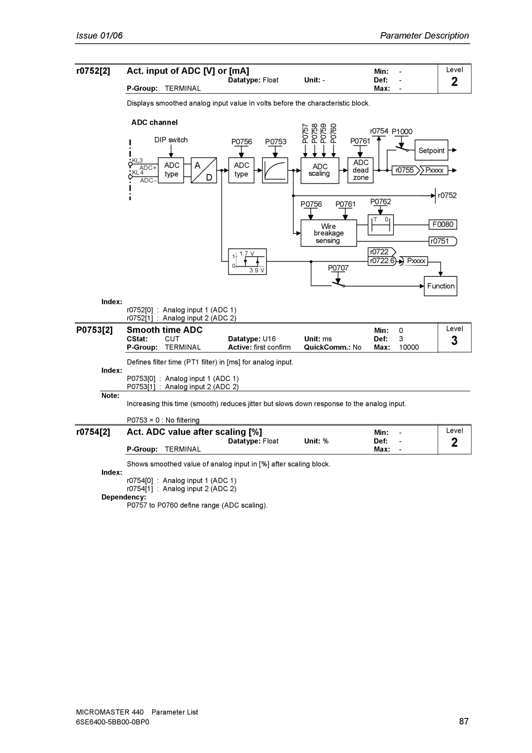
r0752[2] | Act. input of ADC [V] or [mA] |
| Min: | - |
| Datatype: Float | Unit: - | Def: | - |
|
| Max: | - |
Displays smoothed analog input value in volts before the characteristic block.
Level
2
ADC channel
DIP switch
KL3 | ADC |
| A |
|
ADC+ |
|
| ||
KL 4 | type |
|
| D |
ADC− |
|
|
|
P0756 P0753
ADC type
P0757 | P0758 | P0759 | P0760 | P0761 | |
|
|
|
|
| r0754 P1000 |
|
|
|
|
| Setpoint |
| ADC |
| ADC |
| |
|
| dead | r0755 Pxxxx | ||
| scaling | ||||
| zone |
| |||
|
|
|
|
| |
P0756 P0761 P0762
r0752
|
|
| T | 0 |
|
|
| |
|
|
|
|
|
| |||
Wire | F0080 | |||||||
|
|
|
|
|
| |||
|
|
|
|
|
| |||
breakage |
|
|
|
|
|
|
| |
sensing |
|
|
|
|
|
| r0751 |
1 | 1.7 V |
0 | 3 .9 V |
|
P0707
r0722
r0722.6 ![]() Pxxxx
Pxxxx
![]() Function
Function
Index:
r0752[0] : Analog input 1 (ADC 1)
r0752[1] : Analog input 2 (ADC 2)
P0753[2] Smooth time ADC
CStat: | CUT | Datatype: U16 |
TERMINAL | Active: first confirm |
| Min: | 0 | Level |
Unit: ms | Def: | 3 | 3 |
| |||
QuickComm.: No | Max: | 10000 |
|
| Index: | Defines filter time (PT1 filter) in [ms] for analog input. |
|
|
|
| |
| P0753[0] | : Analog input 1 (ADC 1) |
|
|
|
| |
|
|
|
|
|
| ||
|
| P0753[1] | : Analog input 2 (ADC 2) |
|
|
|
|
| Note: | Increasing this time (smooth) reduces jitter but slows down response to the analog input. |
| ||||
|
|
| |||||
|
| P0753 = 0 : No filtering |
|
|
|
| |
r0754[2] | Act. ADC value after scaling [%] |
| Min: | - | Level | ||
|
|
| Datatype: Float | Unit: % | Def: | - | 2 |
|
|
|
| ||||
|
|
|
| Max: | - |
| |
| Index: | Shows smoothed value of analog input in [%] after scaling block. |
|
|
| ||
| r0754[0] | : Analog input 1 (ADC 1) |
|
|
|
| |
|
|
|
|
|
| ||
|
| r0754[1] | : Analog input 2 (ADC 2) |
|
|
|
|
| Dependency: |
|
|
|
|
| |
P0757 to P0760 define range (ADC scaling).
MICROMASTER 440 | Parameter List |
87 |