260
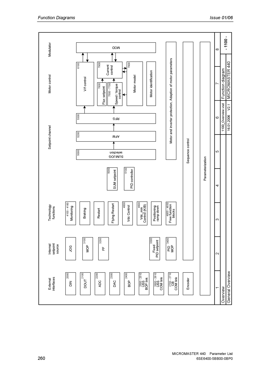
External interfaces
2000
DIN
Internal setpoint source
JOG
Technology
functions
4100 - 4180
Monitoring
Setpoint channel | Motor control | Modulator |
Function Diagrams
2100
DOUT
2200
3100
MOP
Braking
5000
5200
5300
6100
V/f control
ADC
2300
DAC
2400
3200
FF
Restart
Flying Restart
4600
5000
SUM setpoint
5100
SUM/JOG selection
AFM
RFG
7800
Flux setpoint
7500 - 7700
Speed / torque
control
7900
Current control
MOD
MICROMASTER
BOP
2500 - 2510
USS
BOP link
2600 - 2610
USS
COM link
2700 - 2710
CB
COM link
3300
Fixed
PID setpoint
PID 3400
MOP
Vdc Control
Vdc_min4600 Control (KIB)
Positioning ramp down
4800 - 4830
Free function
blocks
PID controller
7900
Motor model
Motor identification
Motor and inverter protection, Adaption of motor parameters
440 Parameter List
| Encoder |
|
|
|
|
| Sequence control |
|
|
|
|
| |
|
|
|
|
|
|
|
|
|
|
|
|
| |
|
|
|
|
|
|
|
|
|
|
|
|
| |
|
|
|
|
|
|
| Parameterization |
|
|
|
|
| |
|
|
|
|
|
|
|
|
|
|
|
|
|
|
|
|
|
|
|
|
|
|
|
|
|
|
|
|
1 |
| 2 | 3 | 4 |
| 5 | 6 | 7 |
| 8 |
| ||
Overview |
|
|
|
|
|
| 1100_Overview.vsd | Function diagram |
| - 1100 - | |||
General Overview |
|
|
|
|
|
| 16.01.2006 V2.1 | MICROMASTER 440 | |||||
|
|
|
|
|
|
|
| ||||||
