Issue 01/06 | Parameter Description |
The actual active drive data set (DDS) is displayed in parameter r0051[1].
|
| selected |
| active | |
|
|
| DDS |
| DDS |
| r0055 |
| r0055 | r0051 [0] | r0051 [1] |
| Bit05 |
| Bit04 |
|
|
1. DDS | 0 |
| 0 | 0 | 0 |
2. DDS | 0 |
| 1 | 1 | 1 |
|
|
|
|
|
|
3. DDS | 1 |
| 0 | 2 | 2 |
3. DDS | 1 |
| 1 | 2 | 2 |
Common Settings:
722.0= Digital input 1 (requires P0701 to be set to 99, BICO)
722.1= Digital input 2 (requires P0702 to be set to 99, BICO)
722.2= Digital input 3 (requires P0703 to be set to 99, BICO)
722.3= Digital input 4 (requires P0704 to be set to 99, BICO)
722.4= Digital input 5 (requires P0705 to be set to 99, BICO)
722.5= Digital input 6 (requires P0706 to be set to 99, BICO)
722.6= Digital input 7 (via analog input 1, requires P0707 to be set to 99)
722.7= Digital input 8 (via analog input 2, requires P0708 to be set to 99)
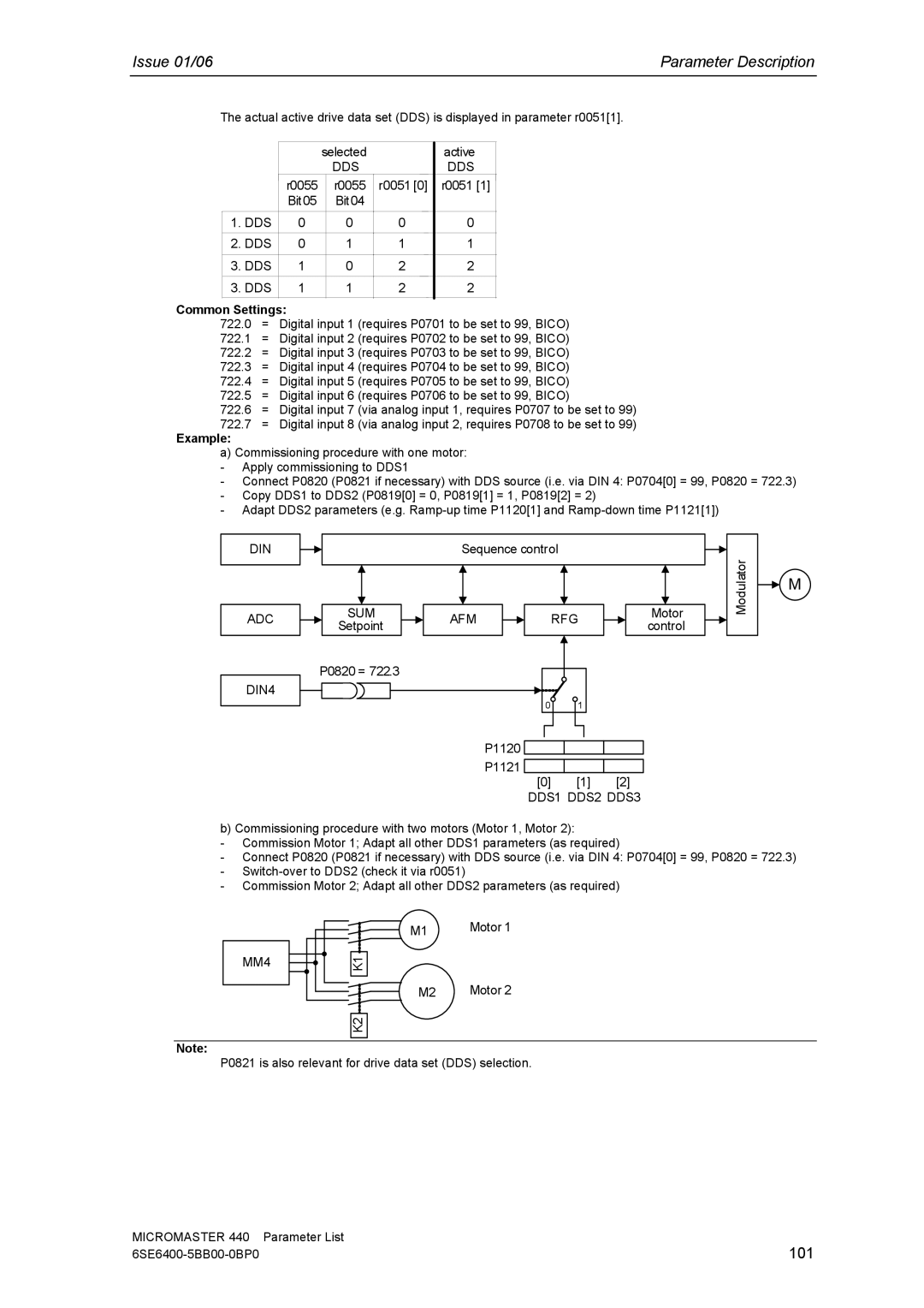
Example:
a) Commissioning procedure with one motor: - Apply commissioning to DDS1
- Connect P0820 (P0821 if necessary) with DDS source (i.e. via DIN 4: P0704[0] = 99, P0820 = 722.3) - Copy DDS1 to DDS2 (P0819[0] = 0, P0819[1] = 1, P0819[2] = 2)
- Adapt DDS2 parameters (e.g.
DIN
Sequence control
ADC
DIN4
SUM
Setpoint
P0820 = 722.3
AFM |
|
| RFG |
|
| Motor |
|
|
|
|
| control |
| ||
|
|
|
| ||||
|
|
|
|
|
|
|
0 | 1 |
P1120
P1121
[0] [1] [2] DDS1 DDS2 DDS3
Modulator
![]() M
M
b) Commissioning procedure with two motors (Motor 1, Motor 2):
-Commission Motor 1; Adapt all other DDS1 parameters (as required)
-Connect P0820 (P0821 if necessary) with DDS source (i.e. via DIN 4: P0704[0] = 99, P0820 = 722.3)
-
-Commission Motor 2; Adapt all other DDS2 parameters (as required)
MM4
M1 | Motor 1 |
K1 |
|
M2 | Motor 2 |
K2 |
|
Note:
P0821 is also relevant for drive data set (DDS) selection.
MICROMASTER 440 | Parameter List |
101 |