Parameter Description | Issue 01/06 |
5 V
ADC
PTC
KTY
Fault |
|
|
|
F0015 |
| P0601 = 2 | & |
|
| ||
|
|
| |
T1 = 4 s |
| No sensor |
|
Signal | 0 |
| |
loss | 1 | PTC |
|
detection | KTY |
| |
| 2 |
| |
|
|
| |
|
| ϑ |
|
| P0601 | V |
|
|
|
| |
Equivalent |
|
|
|
circuit data |
| Thermal | r0631 |
Power dissipation |
| ||
| motor | r0632 | |
PV,mot |
| model | |
|
| ||
|
|
| r0633 |
1![]()
0
r0035
1![]()
0
P0604
| r0052 |
| Bit13 |
≥ 1 | Motor |
temp. | |
| reaction |
| P0610 |
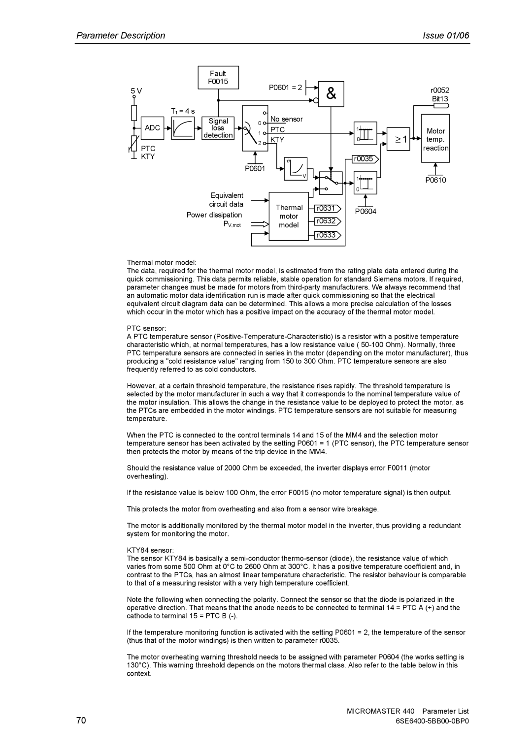
Thermal motor model:
The data, required for the thermal motor model, is estimated from the rating plate data entered during the quick commissioning. This data permits reliable, stable operation for standard Siemens motors. If required, parameter changes must be made for motors from
PTC sensor:
APTC temperature sensor
However, at a certain threshold temperature, the resistance rises rapidly. The threshold temperature is selected by the motor manufacturer in such a way that it corresponds to the nominal temperature value of the motor insulation. This allows the change in the resistance value to be deployed to protect the motor, as the PTCs are embedded in the motor windings. PTC temperature sensors are not suitable for measuring temperature.
When the PTC is connected to the control terminals 14 and 15 of the MM4 and the selection motor temperature sensor has been activated by the setting P0601 = 1 (PTC sensor), the PTC temperature sensor then protects the motor by means of the trip device in the MM4.
Should the resistance value of 2000 Ohm be exceeded, the inverter displays error F0011 (motor overheating).
If the resistance value is below 100 Ohm, the error F0015 (no motor temperature signal) is then output.
This protects the motor from overheating and also from a sensor wire breakage.
The motor is additionally monitored by the thermal motor model in the inverter, thus providing a redundant system for monitoring the motor.
KTY84 sensor:
The sensor KTY84 is basically a
Note the following when connecting the polarity. Connect the sensor so that the diode is polarized in the operative direction. That means that the anode needs to be connected to terminal 14 = PTC A (+) and the cathode to terminal 15 = PTC B
If the temperature monitoring function is activated with the setting P0601 = 2, the temperature of the sensor (thus that of the motor windings) is then written to parameter r0035.
The motor overheating warning threshold needs to be assigned with parameter P0604 (the works setting is 130°C). This warning threshold depends on the motors thermal class. Also refer to the table below in this context.
70 | MICROMASTER 440 Parameter List |