Parameter Description | Issue 01/06 |
r0755[2] | CO: Act. ADC after scal. [4000h] |
| Min: | - |
| Datatype: I16 | Unit: - | Def: | - |
|
|
| Max: | - |
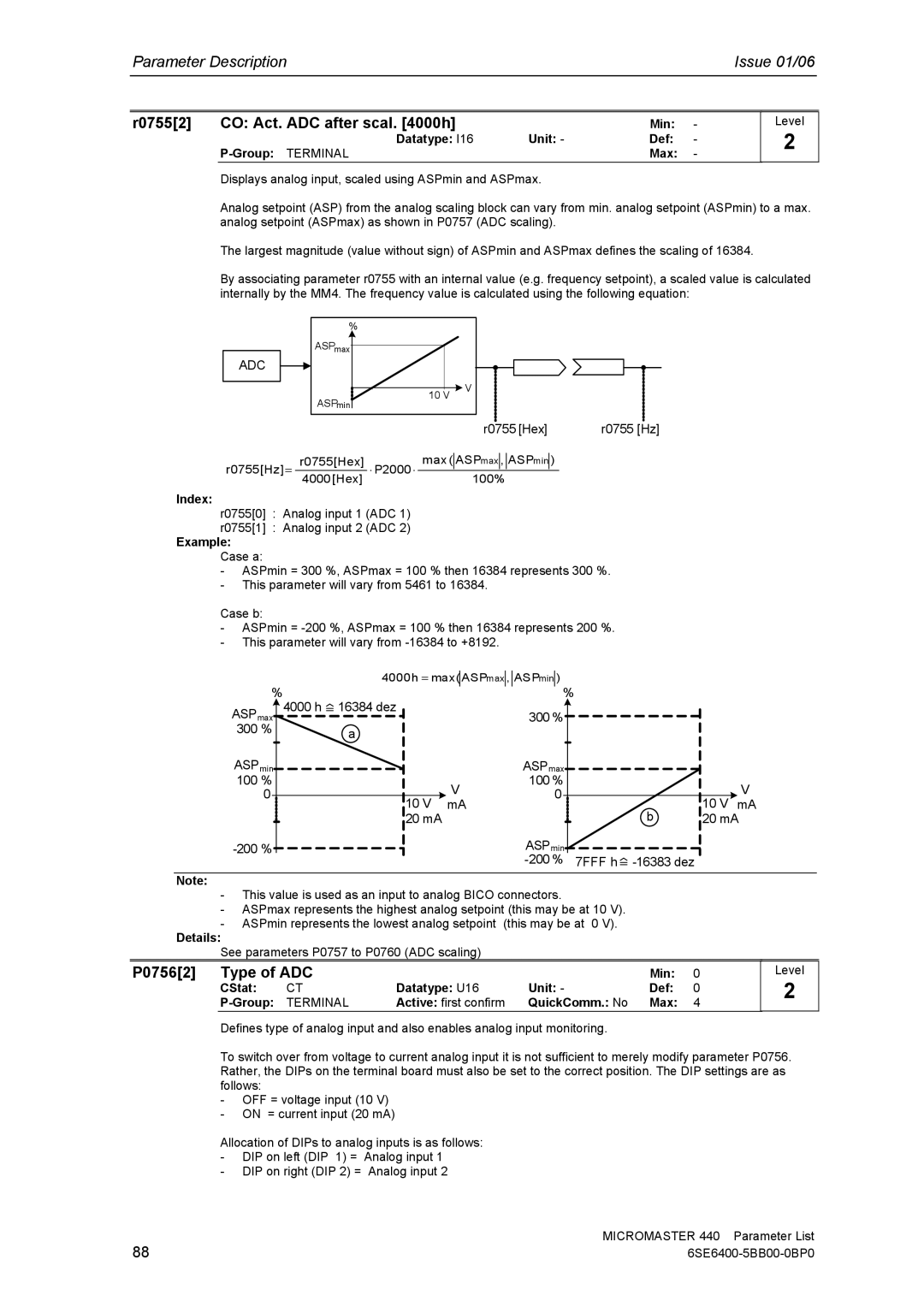
Displays analog input, scaled using ASPmin and ASPmax.
Level
2
Analog setpoint (ASP) from the analog scaling block can vary from min. analog setpoint (ASPmin) to a max. analog setpoint (ASPmax) as shown in P0757 (ADC scaling).
The largest magnitude (value without sign) of ASPmin and ASPmax defines the scaling of 16384.
By associating parameter r0755 with an internal value (e.g. frequency setpoint), a scaled value is calculated internally by the MM4. The frequency value is calculated using the following equation:
ADC
%
ASPmax |
|
10 V | V |
| |
ASPmin |
|
|
|
|
|
| r0755 [Hex] | r0755 [Hz] | ||||||
r0755[Hz] = | r0755[Hex] | ⋅ P2000 ⋅ | max ( |
| ASPmax |
| , |
| ASPmin |
| ) |
|
|
|
|
|
| ||||||||
4000 [Hex] | 100% |
|
|
|
|
| ||||||
|
|
|
|
|
|
| ||||||
Index:
r0755[0] : Analog input 1 (ADC 1)
r0755[1] : Analog input 2 (ADC 2)
Example:
Case a:
-ASPmin = 300 %, ASPmax = 100 % then 16384 represents 300 %.
-This parameter will vary from 5461 to 16384.
Case b:
-ASPmin =
-This parameter will vary from
% | 4000h = max( ASPmax , ASPmin ) |
|
|
| ||
|
| % |
|
|
| |
4000 h | 16384 dez |
| 300 % |
|
|
|
ASPmax |
|
|
|
|
| |
300 % | a |
|
|
|
|
|
|
|
|
|
|
| |
ASPmin |
|
| ASPmax |
|
|
|
100 % |
| V | 100 % |
|
| V |
0 |
| 0 |
|
| ||
10 V | mA |
|
| 10 V mA | ||
|
|
| b | |||
| 20 mA |
|
|
| 20 mA | |
|
| ASPmin | 7FFF h |
| ||
|
|
|
| |||
Note:
-This value is used as an input to analog BICO connectors.
-ASPmax represents the highest analog setpoint (this may be at 10 V).
-ASPmin represents the lowest analog setpoint (this may be at 0 V).
Details:
See parameters P0757 to P0760 (ADC scaling)
P0756[2] | Type of ADC |
|
| Min: | 0 | |
| CStat: | CT | Datatype: U16 | Unit: - | Def: | 0 |
| TERMINAL | Active: first confirm | QuickComm.: No | Max: | 4 | |
Level
2
Defines type of analog input and also enables analog input monitoring.
To switch over from voltage to current analog input it is not sufficient to merely modify parameter P0756. Rather, the DIPs on the terminal board must also be set to the correct position. The DIP settings are as follows:
-OFF = voltage input (10 V)
-ON = current input (20 mA)
Allocation of DIPs to analog inputs is as follows:
-DIP on left (DIP 1) = Analog input 1
-DIP on right (DIP 2) = Analog input 2
88 | MICROMASTER 440 Parameter List |