Issue 01/06 | Parameter Description |
Caution:
If P1245 increased too much, it may interfere with the drive normal operation.
Note:
Vdc max controller automatically increases
Vdc min is activated if
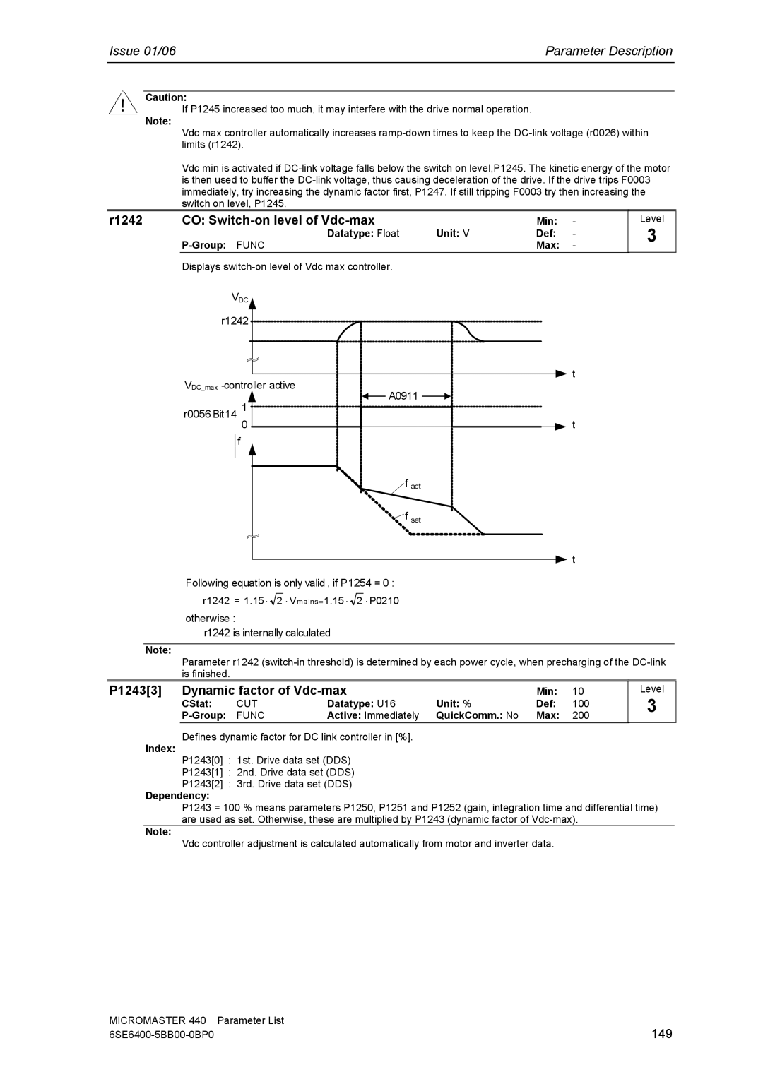
r1242 | CO: |
| Min: | - |
| Datatype: Float | Unit: V | Def: | - |
|
|
| Max: | - |
Displays
VDC
r1242
![]() t
t
VDC_max
r0056 Bit14 1 | A0911 | ||
t | |||
| 0 | ||
| f |
| |
|
|
| |
|
| f act | |
|
| f set | |
|
| t | |
Level
3
Following equation is only valid , if P1254 = 0 :
r1242 = 1.15 ⋅ ![]() 2 ⋅ Vmains= 1.15 ⋅
2 ⋅ Vmains= 1.15 ⋅ ![]() 2 ⋅ P0210
2 ⋅ P0210
otherwise :
r1242 is internally calculated
Note:
Parameter r1242
P1243[3] Dynamic factor of |
| Min: | 10 | ||
CStat: | CUT | Datatype: U16 | Unit: % | Def: | 100 |
FUNC | Active: Immediately | QuickComm.: No | Max: | 200 | |
Defines dynamic factor for DC link controller in [%].
Index:
Level
3
P1243[0] : 1st. Drive data set (DDS)
P1243[1] : 2nd. Drive data set (DDS)
P1243[2] : 3rd. Drive data set (DDS)
Dependency:
P1243 = 100 % means parameters P1250, P1251 and P1252 (gain, integration time and differential time) are used as set. Otherwise, these are multiplied by P1243 (dynamic factor of
Note:
Vdc controller adjustment is calculated automatically from motor and inverter data.
MICROMASTER 440 | Parameter List |
149 |