Issue 01/06 |
|
|
| Parameter Description | |||
|
|
|
|
| |||
P1253[3] |
| Min: | 0.00 | Level | |||
| CStat: | CUT | Datatype: Float | Unit: Hz | Def: | 10.00 | 3 |
|
| ||||||
| FUNC | Active: Immediately | QuickComm.: No | Max: | 600.00 |
| |
Limits maximum effect of Vdc max controller.
Index:
P1253[0] : 1st. Drive data set (DDS)
P1253[1] : 2nd. Drive data set (DDS)
P1253[2] : 3rd. Drive data set (DDS)
P1254 | Auto detect Vdc |
| Min: | 0 | Level | ||
| CStat: | CT | Datatype: U16 | Unit: - | Def: | 1 | 3 |
|
| ||||||
| FUNC | Active: Immediately | QuickComm.: No | Max: | 1 |
| |
Enables/disables
Following
-
-
-
P1254 does not have any effect on the
-
Possible Settings:
0Disabled
1Enabled
Note:
The
P1254 = 0 (Automatic Detection disabled):
The above thresholds are calculated via P0210, if automatic detection is disabled.
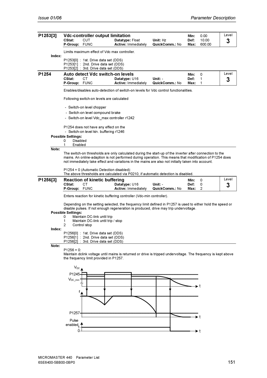
P1256[3] Reaction of kinetic buffering |
| Min: | 0 | ||
CStat: | CT | Datatype: U16 | Unit: - | Def: | 0 |
FUNC | Active: Immediately | QuickComm.: No | Max: | 2 | |
Enters reaction for kinetic buffering controller
Level
3
Depending on the setting selected, the frequency limit defined in P1257 is used to either hold the speed or disable pulses. If not enough regeneration is produced, drive may trip undervoltage.
Possible Settings:
0Maintain
1Maintain
2Control stop
Index:
P1256[0] : 1st. Drive data set (DDS)
P1256[1] : 2nd. Drive data set (DDS)
P1256[2] : 3rd. Drive data set (DDS)
Note:
P1256 = 0:
Maintain dclink voltage until mains is returned or drive is tripped undervoltage. The frequency is kept above the frequency limit provided in P1257.
VDC
P1245![]()
VDC_min![]()
![]() t
t
f |
| |
P1257 | t | |
Pulse | ||
| ||
enabled1 | t | |
0 |
MICROMASTER 440 | Parameter List |
151 |