MICROMASTER 440 Parameter List
|
|
|
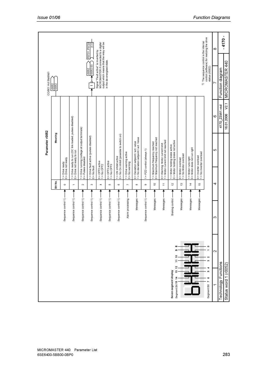
| Parameter r0052 |
|
| Bit No. |
| Meaning |
Sequence control 1) |
| 0 | 1 | = Drive ready |
| 0 | = Drive not ready | ||
| ||||
|
|
| ||
Sequence control 1) |
| 1 | 1 | = Drive ready to run (DC link loaded, pulses disabled) |
| 0 | = Drive not ready to run | ||
|
|
| ||
Sequence control 1) |
| 2 | 1 | = Drive running (voltage at output terminals) |
| 0 | = Pulses disabled | ||
| ||||
|
|
| ||
Sequence control 1) |
| 3 | 1 | = Drive fault active (pulses disabled) |
| 0 | = No fault | ||
|
|
|
CO/BO: Act StatWd1
r0052
r0052
r0052
1 | r0052.03 |
P0731..P0733
(x.x)
Issue 01/06
Segment Bit 15 14 13 12 11 10 9 8
Segment Bit 7 6 | 5 4 | 3 2 | 1 0 |
Sequence control 1) |
| 4 | 0 | = OFF2 active | |
| 1 | = No OFF2 | |||
|
|
|
| ||
|
|
|
|
|
|
Sequence control 1) |
| 5 | 0 | = OFF3 active | |
| 1 | = No OFF3 | |||
| |||||
|
|
|
| ||
|
|
|
|
|
|
Sequence control 1) |
| 6 | 1 | = ON inhibit active | |
| 0 | = No On inhibit (possible to switch on) | |||
| |||||
|
|
|
| ||
|
|
|
|
|
|
Alarm processing |
| 7 | 1 | = Drive warning active | |
| 0 | = No warning | |||
|
|
|
| ||
|
|
|
|
|
|
Messages |
| 8 | 0 | = Deviation setpoint / act. value | |
| 1 | = No deviation setpoint / act. Value | |||
| |||||
|
|
|
| ||
|
|
|
|
| |
Sequence control 1) |
| 9 | 1 = PZD control (always 1) | ||
| |||||
|
|
|
|
|
|
Messages |
| 10 | 1 | = Maximum frequency reached | |
| 0 | = Maximum frequency not reached | |||
|
|
|
| ||
|
|
|
|
|
|
Messages |
| 11 | 0 | = Warning: Motor current limit | |
| 1 | = Motor current limit not reached | |||
| |||||
|
|
|
| ||
|
|
|
|
| |
Braking control |
| 12 | 1 = Motor holding brake active | ||
| 0 = Motor holding brake not active | ||||
| |||||
|
|
|
| ||
|
|
|
|
|
|
Messages |
| 13 | 0 | = Motor overload | |
| 1 | = No Motor overload | |||
|
|
|
| ||
|
|
|
|
|
|
Messages |
| 14 | 1 | = Motor runs right | |
| 0 | = Motor does not run right | |||
| |||||
|
|
|
| ||
|
|
|
|
|
|
Messages |
| 15 | 0 | = Inverter overload | |
| 1 | = No inverter overload | |||
| |||||
|
|
|
| ||
Signal "Fault active" is inverted by MICROMASTER if connected to a digital output which means that the relay will be in the
1)The sequence control is the internal control (software) for realizing the drive status (r0002)
Function
283
1 |
| 2 | 3 | 4 | 5 | 6 | 7 |
| 8 |
Technology Functions |
|
|
|
| 4170_ZSW1.vsd | Function diagram |
| - 4170 - | |
Status word 1 (r0052) |
|
|
|
| 16.01.2006 V2.1 | MICROMASTER 440 | |||
|
|
|
|
| |||||