Issue 01/06 | Parameter Description |
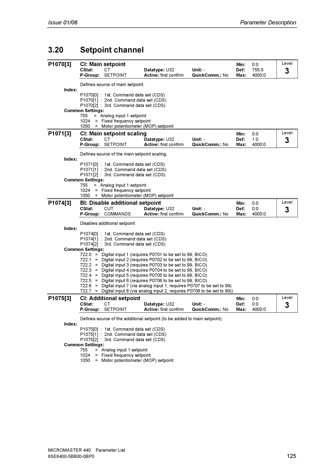
3.20Setpoint channel
P1070[3] | CI: Main setpoint |
|
| Min: | 0:0 | |
| CStat: | CT | Datatype: U32 | Unit: - | Def: | 755:0 |
| SETPOINT | Active: first confirm | QuickComm.: No | Max: | 4000:0 | |
Level
3
Defines source of main setpoint. | |
Index: |
|
P1070[0] : 1st. Command data set (CDS) | |
P1070[1] : 2nd. Command data set (CDS) | |
P1070[2] : 3rd. Command data set (CDS) | |
Common Settings: | |
755 | = Analog input 1 setpoint |
1024 | = Fixed frequency setpoint |
1050 | = Motor potentiometer (MOP) setpoint |
P1071[3] | CI: Main setpoint scaling |
| Min: | 0:0 | Level | |||
| CStat: |
| CT | Datatype: U32 | Unit: - | Def: | 1:0 | 3 |
| SETPOINT | Active: first confirm | QuickComm.: No | Max: | 4000:0 |
| ||
Index: | Defines source of the main setpoint scaling. |
|
|
|
| |||
P1071[0] : 1st. Command data set (CDS) |
|
|
|
| ||||
|
|
|
|
| ||||
| P1071[1] : 2nd. Command data set (CDS) |
|
|
|
| |||
| P1071[2] : 3rd. Command data set (CDS) |
|
|
|
| |||
Common Settings: |
|
|
|
|
| |||
| 755 | = | Analog input 1 setpoint |
|
|
|
| |
| 1024 | = | Fixed frequency setpoint |
|
|
|
| |
| 1050 | = | Motor potentiometer (MOP) setpoint |
|
|
|
| |
P1074[3] | BI: Disable additional setpoint |
| Min: | 0:0 | Level | |||
| CStat: |
| CUT | Datatype: U32 | Unit: - | Def: | 0:0 | 3 |
|
|
| ||||||
| COMMANDS | Active: first confirm | QuickComm.: No | Max: | 4000:0 |
| ||
Disables additional setpoint
Index:
P1074[0] : 1st. Command data set (CDS)
P1074[1] : 2nd. Command data set (CDS)
P1074[2] : 3rd. Command data set (CDS)
Common Settings:
722.0= Digital input 1 (requires P0701 to be set to 99, BICO)
722.1= Digital input 2 (requires P0702 to be set to 99, BICO)
722.2= Digital input 3 (requires P0703 to be set to 99, BICO)
722.3= Digital input 4 (requires P0704 to be set to 99, BICO)
722.4= Digital input 5 (requires P0705 to be set to 99, BICO)
722.5= Digital input 6 (requires P0706 to be set to 99, BICO)
722.6= Digital input 7 (via analog input 1, requires P0707 to be set to 99)
722.7= Digital input 8 (via analog input 2, requires P0708 to be set to 99))
P1075[3] | CI: Additional setpoint |
|
| Min: | 0:0 | |
| CStat: | CT | Datatype: U32 | Unit: - | Def: | 0:0 |
| SETPOINT | Active: first confirm | QuickComm.: No | Max: | 4000:0 | |
Defines source of the additional setpoint (to be added to main setpoint).
Index:
P1075[0] : | 1st. Command data set (CDS) | |
P1075[1] | : | 2nd. Command data set (CDS) |
P1075[2] | : | 3rd. Command data set (CDS) |
Common Settings:
755 | = Analog input 1 setpoint | |
1024 | = | Fixed frequency setpoint |
1050 | = | Motor potentiometer (MOP) setpoint |
Level
3
MICROMASTER 440 | Parameter List |
125 |
