Parameter Description | Issue 01/06 |
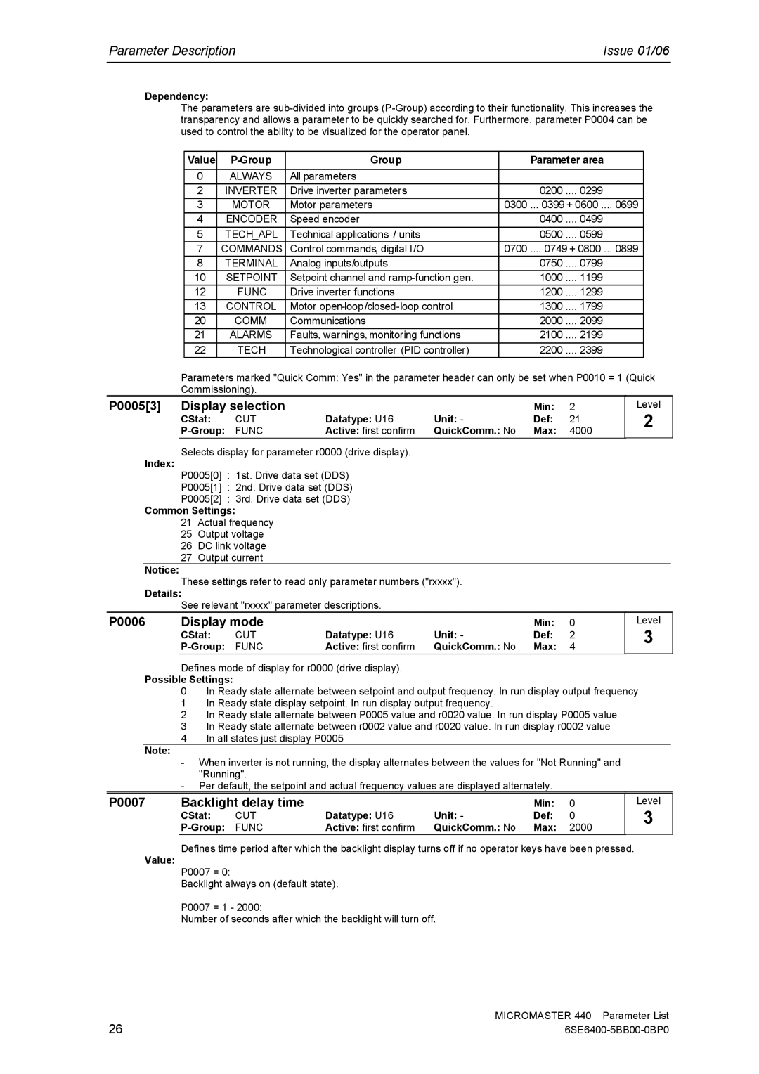
Dependency:
The parameters are
Value |
| Group |
| Parameter area |
| |
|
|
|
|
|
|
|
0 | ALWAYS | All parameters |
|
|
|
|
2 | INVERTER | Drive inverter parameters |
| 0200 .... | 0299 |
|
3 | MOTOR | Motor parameters | 0300 | ... 0399 + 0600 .... | 0699 | |
4 | ENCODER | Speed encoder |
| 0400 .... | 0499 |
|
5 | TECH_APL | Technical applications / units |
| 0500 .... | 0599 |
|
7 | COMMANDS | Control commands, digital I/O | 0700 | .... 0749 + 0800 ... | 0899 | |
8 | TERMINAL | Analog inputs/outputs |
| 0750 .... | 0799 |
|
10 | SETPOINT | Setpoint channel and |
| 1000 .... | 1199 |
|
12 | FUNC | Drive inverter functions |
| 1200 .... | 1299 |
|
13 | CONTROL | Motor |
| 1300 .... | 1799 |
|
20 | COMM | Communications |
| 2000 .... | 2099 |
|
21 | ALARMS | Faults, warnings, monitoring functions |
| 2100 .... | 2199 |
|
22 | TECH | Technological controller (PID controller) |
| 2200 .... | 2399 |
|
Parameters marked "Quick Comm: Yes" in the parameter header can only be set when P0010 = 1 (Quick Commissioning).
P0005[3] | Display selection |
|
| Min: | 2 | |
| CStat: | CUT | Datatype: U16 | Unit: - | Def: | 21 |
| FUNC | Active: first confirm | QuickComm.: No | Max: | 4000 | |
Level
2
Selects display for parameter r0000 (drive display).
Index:
P0005[0] : 1st. Drive data set (DDS)
P0005[1] : 2nd. Drive data set (DDS)
P0005[2] : 3rd. Drive data set (DDS)
Common Settings:
21Actual frequency
25Output voltage
26DC link voltage
27Output current
Notice:
These settings refer to read only parameter numbers ("rxxxx").
Details:
See relevant "rxxxx" parameter descriptions.
P0006 | Display mode |
|
| Min: | 0 | |
| CStat: | CUT | Datatype: U16 | Unit: - | Def: | 2 |
| FUNC | Active: first confirm | QuickComm.: No | Max: | 4 | |
Level
3
Defines mode of display for r0000 (drive display).
Possible Settings:
0In Ready state alternate between setpoint and output frequency. In run display output frequency
1In Ready state display setpoint. In run display output frequency.
2In Ready state alternate between P0005 value and r0020 value. In run display P0005 value
3In Ready state alternate between r0002 value and r0020 value. In run display r0002 value
4In all states just display P0005
Note:
-When inverter is not running, the display alternates between the values for "Not Running" and "Running".
-Per default, the setpoint and actual frequency values are displayed alternately.
P0007 | Backlight delay time |
|
| Min: | 0 | |
| CStat: | CUT | Datatype: U16 | Unit: - | Def: | 0 |
| FUNC | Active: first confirm | QuickComm.: No | Max: | 2000 | |
Level
3
Defines time period after which the backlight display turns off if no operator keys have been pressed.
Value:
P0007 = 0:
Backlight always on (default state).
P0007 = 1 - 2000:
Number of seconds after which the backlight will turn off.
26 | MICROMASTER 440 Parameter List |