Parameters | Issue 01/06 |
2 Parameters
2.1Introduction to MICROMASTER System Parameters
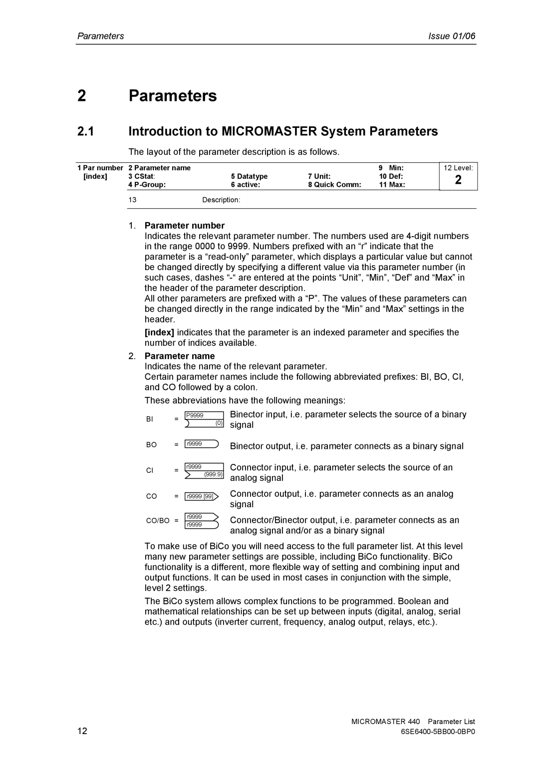
The layout of the parameter description is as follows.
1 Par number | 2 Parameter name |
|
|
| 9 | Min: | |
[index] | 3 | CStat: | 5 Datatype | 7 | Unit: | 10 | Def: |
| 4 | 6 active: | 8 | Quick Comm: | 11 | Max: | |
| 13 | Description: |
|
|
|
| |
12 Level:
2
1.Parameter number
Indicates the relevant parameter number. The numbers used are
All other parameters are prefixed with a “P”. The values of these parameters can be changed directly in the range indicated by the “Min” and “Max” settings in the header.
[index] indicates that the parameter is an indexed parameter and specifies the number of indices available.
2.Parameter name
Indicates the name of the relevant parameter.
Certain parameter names include the following abbreviated prefixes: BI, BO, CI, and CO followed by a colon.
These abbreviations have the following meanings:
BI =
BO =
CI =
CO =
P9999
(0)
r9999
r9999
(999:9)
r9999 [99]
Binector input, i.e. parameter selects the source of a binary signal
Binector output, i.e. parameter connects as a binary signal
Connector input, i.e. parameter selects the source of an analog signal
Connector output, i.e. parameter connects as an analog signal
CO/BO = r9999 r9999
Connector/Binector output, i.e. parameter connects as an analog signal and/or as a binary signal
To make use of BiCo you will need access to the full parameter list. At this level many new parameter settings are possible, including BiCo functionality. BiCo functionality is a different, more flexible way of setting and combining input and output functions. It can be used in most cases in conjunction with the simple, level 2 settings.
The BiCo system allows complex functions to be programmed. Boolean and mathematical relationships can be set up between inputs (digital, analog, serial etc.) and outputs (inverter current, frequency, analog output, relays, etc.).
12 | MICROMASTER 440 Parameter List |