Issue 01/06 | Parameter Description |
3.2Diagnosis parameters
r0018 | Firmware version |
| Min: | - |
| Datatype: Float | Unit: - | Def: | - |
|
| Max: | - |
Displays version number of installed firmware.
Level
1
r0019 | CO/BO: BOP control word |
| Min: | - |
| Datatype: U16 | Unit: - | Def: | - |
|
| Max: | - |
Displays status of operator panel commands.
Level
3
The settings below are used as the "source" codes for keypad control when connecting to BICO input parameters.
Bitfields: |
|
|
|
|
|
Bit00 | ON/OFF1 | 0 | NO | 1 | YES |
Bit01 | OFF2: Electrical stop | 0 | YES | 1 | NO |
Bit08 | JOG right | 0 | NO | 1 | YES |
Bit11 | Reverse (setpoint inversion) | 0 | NO | 1 | YES |
Bit13 | Motor potentiometer MOP up | 0 | NO | 1 | YES |
Bit14 | Motor potentiometer MOP down | 0 | NO | 1 | YES |
Note:
When BICO technology is used to allocate functions to panel buttons, this parameter displays the actual status of the relevant command.
The following functions can be "connected" to individual buttons:
-ON/OFF1,
-OFF2,
-JOG,
-REVERSE,
-INCREASE,
-DECREASE
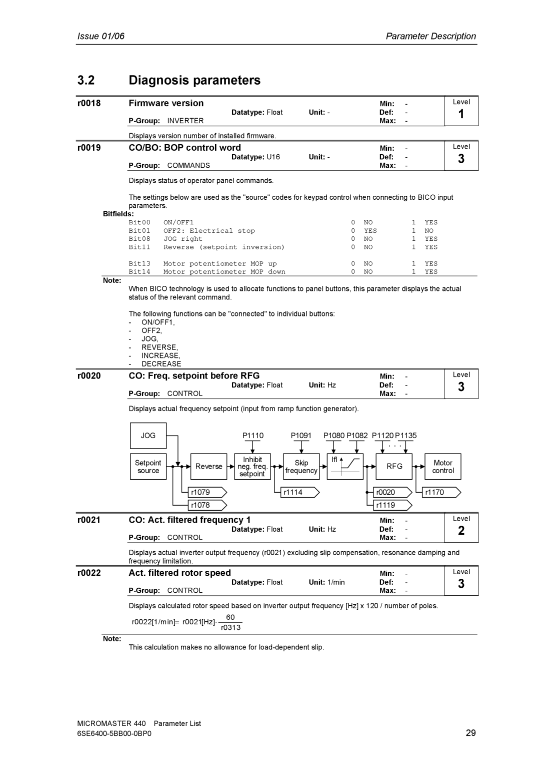
r0020 | CO: Freq. setpoint before RFG |
| Min: | - |
| Datatype: Float | Unit: Hz | Def: | - |
|
|
| Max: | - |
Displays actual frequency setpoint (input from ramp function generator).
Level
3
JOG
Setpoint source
| P1110 | P1091 | |
Reverse | Inhibit | Skip | |
neg. freq. | |||
frequency | |||
| setpoint | ||
|
| ||
r1079 |
| r1114 | |
r1078 |
|
|
P1080 P1082 P1120 P1135
. . .
IfI ![]()
RFG
![]() r0020 r1119
r0020 r1119
Motor control
r1170
r0021 | CO: Act. filtered frequency 1 |
| Min: | - |
| Datatype: Float | Unit: Hz | Def: | - |
|
| Max: | - |
Level
2
Displays actual inverter output frequency (r0021) excluding slip compensation, resonance damping and frequency limitation.
r0022 | Act. filtered rotor speed |
| Min: | - |
| Datatype: Float | Unit: 1/min | Def: | - |
|
|
| Max: | - |
Level
3
Displays calculated rotor speed based on inverter output frequency [Hz] x 120 / number of poles.
r0022[1/min]= r0021[Hz]⋅ 60
r0313
Note:
This calculation makes no allowance for
MICROMASTER 440 | Parameter List |
29 |