Issue 01/06 | Parameter Description |
r2114[2] | Run time counter |
| Min: | - |
| Datatype: U16 | Unit: - | Def: | - |
|
| Max: | - |
Displays run time counter.
Level
3
It is the total time the drive has been powered up. When power goes value is saved, then restored on powerup. The run time counter r2114 will be calculate as followed:
-Multiply the value in r2114[0], by 65536 and then add it to the value in r2114[1].
-The resultant answer will be in seconds.
When AOP is not connected, the time in this parameter is used by r0948 to indicate when a fault has occured.
Index:
r2114[0] : System Time, Seconds, Upper Word
r2114[1] : System Time, Seconds, Lower Word
Example:
If r2114[0] = 1 & r2114[1] = 20864
We get 1 * 65536 + 20864 = 86400 seconds which equals 1 day.
P2115[3] AOP real time clock |
|
| Min: | 0 | |
CStat: | CT | Datatype: U16 | Unit: - | Def: | 0 |
ALARMS | Active: Immediately | QuickComm.: No | Max: | 65535 | |
Displays AOP real time.
Level
3
All of the frequency inverters have an internal time generator function which is used to
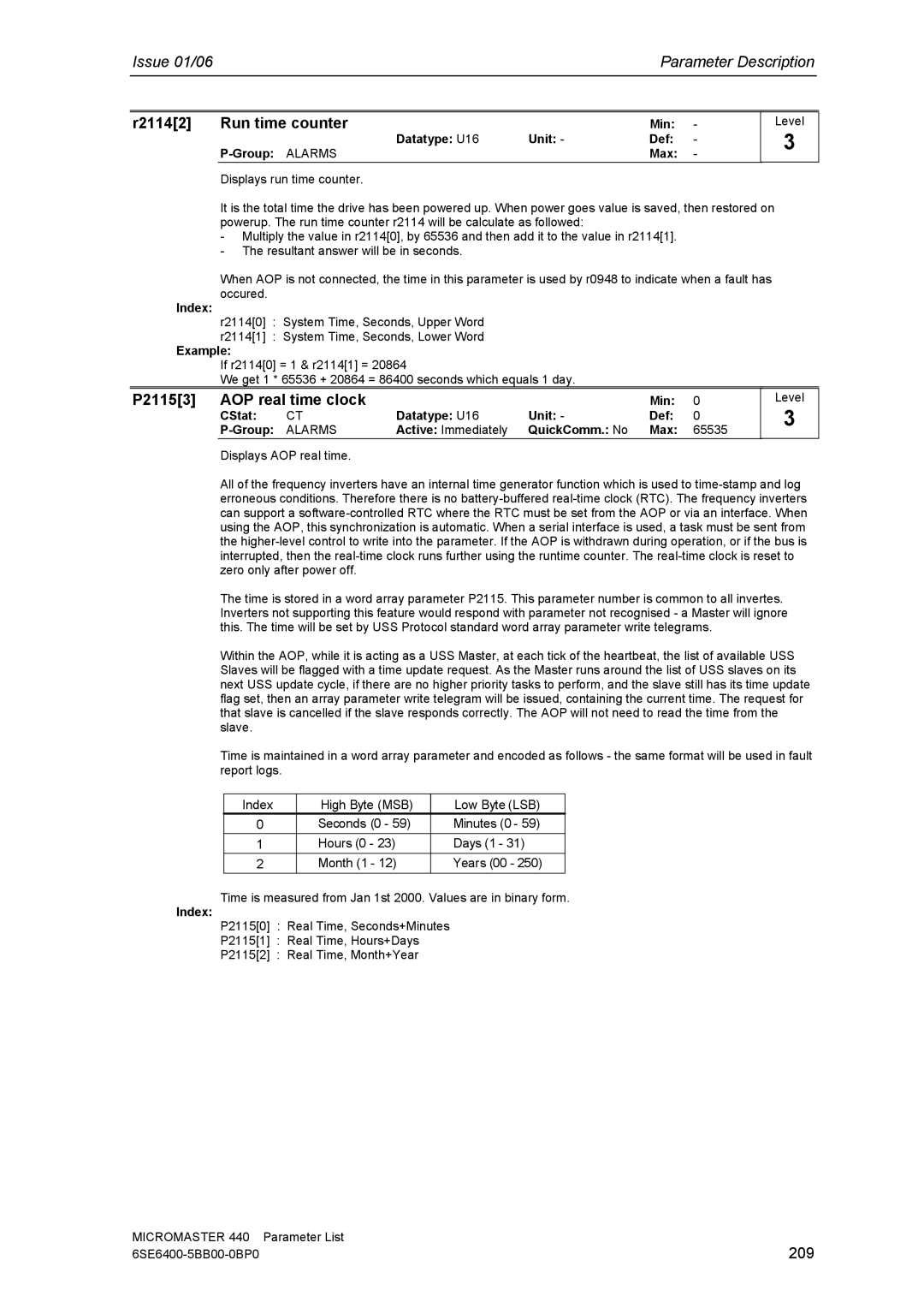
The time is stored in a word array parameter P2115. This parameter number is common to all invertes. Inverters not supporting this feature would respond with parameter not recognised - a Master will ignore this. The time will be set by USS Protocol standard word array parameter write telegrams.
Within the AOP, while it is acting as a USS Master, at each tick of the heartbeat, the list of available USS Slaves will be flagged with a time update request. As the Master runs around the list of USS slaves on its next USS update cycle, if there are no higher priority tasks to perform, and the slave still has its time update flag set, then an array parameter write telegram will be issued, containing the current time. The request for that slave is cancelled if the slave responds correctly. The AOP will not need to read the time from the slave.
Time is maintained in a word array parameter and encoded as follows - the same format will be used in fault report logs.
Index | High Byte (MSB) | Low Byte (LSB) |
0 | Seconds (0 - 59) | Minutes (0 - 59) |
1 | Hours (0 - 23) | Days (1 - 31) |
2 | Month (1 - 12) | Years (00 - 250) |
Time is measured from Jan 1st 2000. Values are in binary form.
Index:
P2115[0] : Real Time, Seconds+Minutes
P2115[1] : Real Time, Hours+Days
P2115[2] : Real Time, Month+Year
MICROMASTER 440 | Parameter List |
209 |
