266
Fn
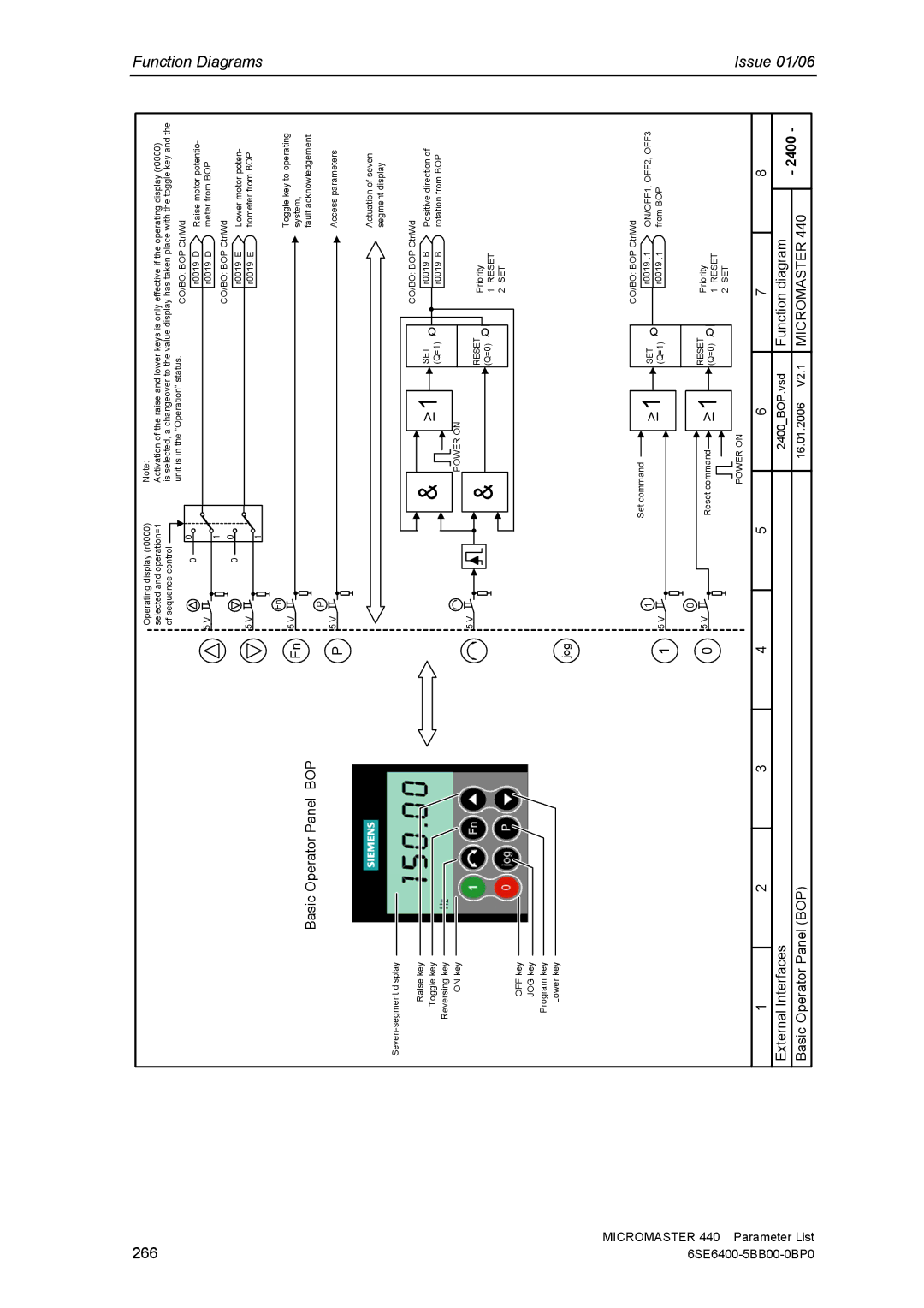
Basic Operator Panel BOP
P
Operating display (r0000) selected and operation=1 of sequence control
0 | 0 |
| |
5 V | 1 |
| |
0 | 0 |
| |
5 V | 1 |
|
Fn
5 V
P
5 V
Note:
Activation of the raise and lower keys is only effective if the operating display (r0000)
is selected, a changeover to the value display has taken place with the toggle key and the
unit is in the "Operation" status. | CO/BO: BOP CtrlWd | |
| r0019 .D | Raise motor potentio- |
| r0019 .D | meter from BOP |
| CO/BO: BOP CtrlWd | |
| r0019 .E | Lower motor poten- |
| r0019 .E | tiometer from BOP |
|
|
|
Toggle key to operating system,
fault acknowledgement Access parameters
Actuation of seven- segment display
Function Diagrams
Raise key
Toggle key
Reversing key
ON key
OFF key
JOG key
Program key
Lower key
jog
| & | 1 |
|
| CO/BO: BOP CtrlWd | ||
| SET | Q |
| r0019 .B | Positive direction of | ||
| (Q=1) |
| r0019 .B | rotation from BOP | |||
|
| POWER ON |
|
|
|
|
|
5 V | & |
| RESET |
| Priority |
| |
|
| Q |
| ||||
|
| (Q=0) | 1 | RESET |
| ||
|
|
|
| ||||
|
|
|
|
| 2 | SET |
|
MICROMASTER 440 6SE6400-
1
0
1
5 V
0
5 V
|
| Set command |
| 1 |
|
| SET | ||||
|
|
|
|
|
|
| |||||
|
|
|
|
|
|
|
|
|
| ||
|
|
|
|
|
|
|
|
|
| (Q=1) | |
|
|
|
|
|
|
|
|
|
|
|
|
|
|
|
|
|
|
|
|
|
|
|
|
|
| Reset command |
|
| 1 |
|
| RESET | |||
|
|
|
|
|
| ||||||
|
|
|
|
|
| (Q=0) | |||||
|
|
|
| ||||||||
|
|
|
|
|
|
|
|
|
| ||
|
|
|
|
|
|
|
|
|
|
|
|
POWER ON
Q Q![]()
CO/BO: BOP CtrlWd
r0019 .1 ON/OFF1, OFF2, OFF3
r0019 .1 | from BOP |
Priority
1RESET
2SET
Parameter List
1 | 2 | 3 | 4 | 5 | 6 | 7 |
| 8 |
External Interfaces |
|
|
|
| 2400_BOP.vsd | Function diagram |
| - 2400 - |
Basic Operator Panel (BOP) |
|
|
| 16.01.2006 V2.1 | MICROMASTER 440 | |||
|
|
|
| |||||
